Kia Rio: Heating,Ventilation, Air Conditioning
Specifications
| Specification |
Air Conditioner
|
Item |
Specification |
|
|
Compressor |
Type |
DVE12 |
|
Oil type & Capacity |
PAG 30, 120 ± 10 g |
|
|
Displacement |
122 cc/rev |
|
|
Expansion valve |
Type |
Block type |
|
Refrigerant |
Type |
R-134a, R-1234yf |
|
Capacity |
450 ± 25 g (15.7 ± 0.88 oz.) |
|
Blower Unit
|
Item |
Specification |
|
|
Intake |
Control Type |
Dome door |
|
Blower |
Type |
Sirocco |
|
Speed Step |
FATC: Auto or 1-8 speed, MANUAL: 1-4 speed |
|
|
Speed Control |
FATC: Power mosfet, MANUAL: Blower resistor |
|
|
Air filter |
Type |
Particle filter |
Heater And Evaporator Unit
|
Item |
Specification |
|
|
Heater |
Type |
Pin & Tube type |
|
Heating Capacity |
4,700 - 3% kcal/hr |
|
|
Mode Control Type |
Actuator |
|
|
Temperature Control Type |
Actuator |
|
|
Evaporator |
Cooling Capacity |
4,500 kcal/hr |
|
Temperature Control Type |
Evaporator temperature sensor |
|
|
A/C ON/OFF |
ON: 0 ± 0.3°C (32.0 ± 0.5°F) OFF: -2.0 ± 0.3°C (28.4 ± 0.5°F) |
|
Tightening Torques
|
Items |
N·m |
kgf·m |
lb·ft |
|
Compressor |
21.6 - 32.4 |
2.2 - 3.3 |
15.9 - 23.8 |
|
Condenser - Discharge hose |
4.9 - 5.9 |
0.5 - 0.6 |
3.6 - 4.3 |
|
Condenser - Liquid tube |
|||
|
Compressor - Discharge hose |
4.9 - 5.9 |
0.5 - 0.6 |
3.6 - 4.3 |
|
Compressor - Suction hose |
|||
|
Expansion valve - Evaporator |
11.8 - 14.7 |
1.2 - 1.5 |
8.7 - 10.9 |
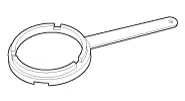
Special service tools
| Special Service Tools |
|
Tool (Number and name) |
Illustration |
Use |
|
09977-3R000 Disc & hub assembly bolt remover |
|
Removal and installation of disc & hub assembly. |
Troubleshooting
| Troubleshooting |
| Problem Symptoms Table |
Before replacing or repairing air conditioning components, first determine if the malfunction is due to the refrigerant charge, air flow or compressor.
Use the table below to help you find the cause of the problem. The numbers indicate the priority of the likely cause of the problem. Check each part in order. If necessary, replace these parts.
After correcting the malfunction, check the complete system to ensure that performance is satisfactory.
|
Symptom |
Suspect Area |
|
No blower operation |
1. Blower fuse |
|
2. Blower relay |
|
|
3. Blower motor |
|
|
4. Blower resistor, Power mosfet or PWM blower module |
|
|
5. Blower speed control switch or knob |
|
|
6. Wire harness |
|
|
No air temperature control |
1. Engine coolant capacity |
|
2. Heater control assembly |
|
|
3. Temperature control actuator or cable |
|
|
No compressor operation |
1. Refrigerant capacity |
|
2. A/C Fuse |
|
|
3. Compressor |
|
|
4. A/C pressure transducer |
|
|
5. A/C switch |
|
|
6. Evaporator temperature sensor |
|
|
7. Wire harness |
|
|
8. High CAN |
|
|
No cool comes out |
1. Refrigerant capacity |
|
2. Refrigerant pressure |
|
|
3. Drive belt |
|
|
4. Compressor |
|
|
5. A/C pressure transducer |
|
|
6. Evaporator temperature sensor |
|
|
7. A/C switch |
|
|
8. Heater control assembly |
|
|
9. Wire harness |
|
|
10. High CAN |
|
|
11. Temperature control actuator or cable |
|
|
Insufficient cooling |
1. Refrigerant capacity |
|
2. Drive belt |
|
|
3. Compressor |
|
|
4. Condenser |
|
|
5. Expansion valve |
|
|
6. Evaporator |
|
|
7. Refrigerant lines |
|
|
8. A/C pressure transducer |
|
|
9. Heater control assembly |
|
|
10. High CAN |
|
|
No engine idle-up when A/C switch ON |
1. Engine ECM |
|
2. Wire harness |
|
|
No air inlet control |
1. Heater control assembly |
|
2. Intake actuator |
|
|
No mode control |
1. Heater control assembly |
|
2. Mode control actuator or cable |
|
|
No cooling fan operation |
1. Cooling fan fuse |
|
2. Fan motor |
|
|
3. Blower resistor, Power mosfet or PWM blower module |
|
|
4. Engine ECM |
|
|
5. Wire harness |
- Air Conditioning System
- Compressor Oil
- Refrigerant line
- Compressor
- Condenser
- Receiver-Drier
- A/C Pressure Transducer
- Evaporator Temperature Sensor
- Photo Sensor (FATC only)
- Ambient Temperature Sensor
- Heater
- Blower
- Blower Unit
- Blower Motor
- Blower Resistor (MANUAL)
- Power Mosfet (FATC)
- Climate Control Air Filtar
- Intake Actuator
- Controller
Components and components location Components Schematic diagrams Circuit Diagram Description and operation Description Integrated Rain Sensor Integrated rain sensor (A) controls three systems: front wiper, auto-light, and central air conditioner.
General safety information and caution Instructions When Handling Refrigerant 1. R-134a liquid refrigerant is highly volatile.
Other information:
Kia Rio 2017-2023 YB Service Manual: Immobilizer System
Schematic diagrams Circuit Diaram Description and operation Description The immobilizer system will disable the vehicle unless the proper ignition key is used, in addition to the currently available anti-theft systems such as car alarms, the immobilizer system aims to drastically reduce the rate of auto theft.
Kia Rio 2017-2023 YB Service Manual: Power Door Mirror Actuator
Components and components location Components 1. Side repeater lamp Repair procedures Inspection 1. Disconnect the negative (-) battery terminal. 2. Remove the front door quadrant inner cover (A).
Categories
- Manuals Home
- Kia Rio Owners Manual
- Kia Rio Service Manual
- Brake System
- Suspension System
- Maintenance
- New on site
- Most important about car
