Kia Rio: Heater / Temperature Control Actuator
Description and operation
| Description |
The heater unit includes mode control actuator and temperature control actuator.
The temperature control actuator is located at the heater unit. It regulates the temperature by the procedure as follows. Signal from control unit adjusts position of temperature door by operating temperature switch and then temperature will be regulated by the hot/cold air ratio decided by position of temperature door.
Repair procedures
| Inspection |
| 1. |
Turn the ignition switch OFF. |
| 2. |
Disconnect the temperature control actuator connector. |
| 3. |
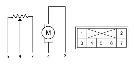
Verify that the temperature control actuator operates to the warm (LHD) or cool (RHD) position when connecting 12V to the terminal 3 and grounding terminal 4. Verify that the temperature control actuator operates to the cool (LHD) or warm (RHD) position when connecting in the reverse.
|
| 4. |
Connect the temperature control actuator connector. |
| 5. |
Turn the ignition switch ON. |
| 6. |
Check the voltage between terminal 6 and 5 (LHD) or 7 (RHD). Specification
It will feedback current position of actuator to controls. |
| 7. |
If the measured voltage is not specification, substitute with a known-good temperature control actuator and check for proper operation. |
| 8. |
If the problem is corrected, replace the temperature control actuator. |
| Replacement |
| 1. |
Disconnect the negative (-) battery terminal. |
| 2. |
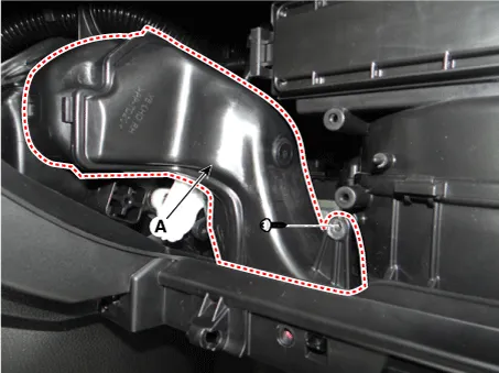
Remove the driver side shower duct (A) after loosening the screw.
|
| 3. |
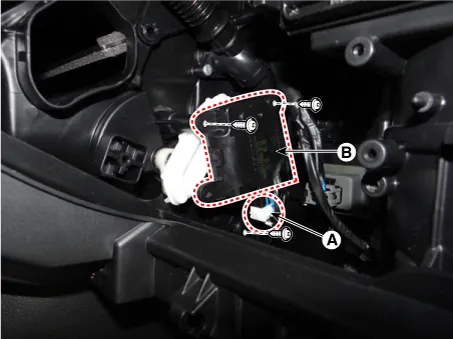
Disconnect the connector (A) and then remove the temperature control actuator (B) after loosening the mounting screws.
|
| 4. |
Installation is the reverse order of removal. |
Components and components location Component Location Components 1. Heater pipe cover 2. Heater core 3.
Description and operation Description The mode control actuator is located at the heater unit. It adjusts position of mode door by operating mode control actuator based on signal of A/C control unit.
Other information:
Kia Rio 2017-2023 YB Service Manual: Lane Departure Warning System (LDWS)
Components and components location Components 1. LDWS ON/OFF switch 2. Instrument cluster 3. LDWS unit (MFC) ※ MFC : Multi Function Camera – Function : LDWS, HBA, AEB Description and operation Description System block diagram Components of LDWS
Kia Rio 2017-2023 YB Service Manual: Compressor Oil
Repair procedures Oil Specification 1. The HFC-134a system requires synthetic compressor oil (PAG) whereas the R-12 system requires mineral compressor oil. The two oils must never be mixed. 2. Compressor oil (PAG) varies according to compressor model.
Categories
- Manuals Home
- Kia Rio Owners Manual
- Kia Rio Service Manual
- Coolant
- Maintenance
- Engine Electrical System
- New on site
- Most important about car
