Kia Rio: Lighting System / Rear Combination Lamp
Repair procedures
| Removal |
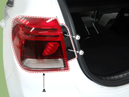
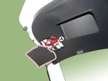
Rear Combination Lamp (Outside)
| 1. |
Disconnect the negative (-) battery terminal. |
| 2. |
Remove the rear combination lamp (A) after loosening the mounting screws.
|
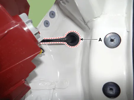
| 3. |
Remove the rear combination lamp packing (A).
|
| 4. |
Disconnect the rear combination lamp connector (A).
|

| Bulb Replacement |
Turn Signal Lamp
| 1. |
Turn the headlamp switch off. |
| 2. |
Remove the rear combination lamp (outside). |
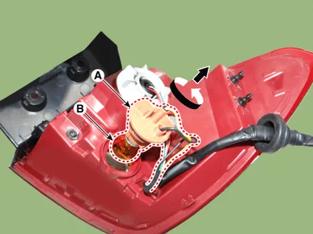
| 3. |
Remove the turn signal lamp bulb (B) by turning the socket (A) counterclockwise.
|
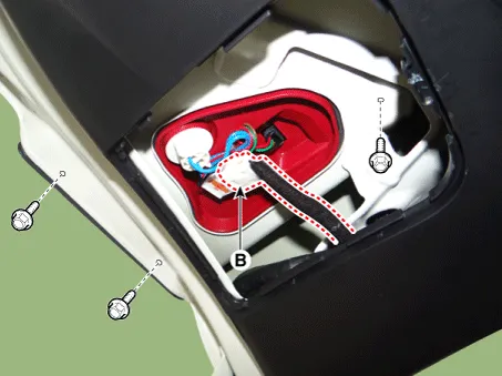
Rear Combination Lamp (Inside)
| 1. |
Disconnect the negative (-) battery terminal. |
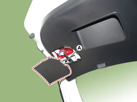
| 2. |
Using a screwdriver or remover, remove the rear combination lamp cover (A).
|
| 3. |
Disconnect the connector (B) and then remove the rear combination lamp (A) after loosening the nuts.
|

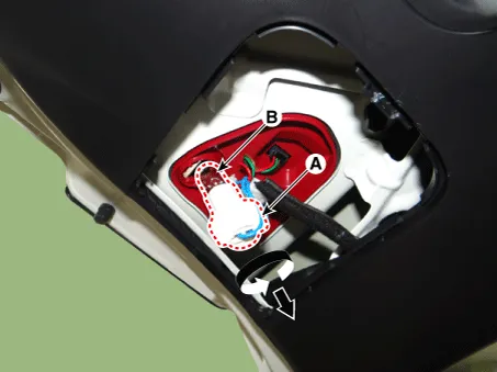
| Bulb Replacement |
Back up lamp
| 1. |
Using a screwdriver or remover, remove the rear combination lamp cover (A).
|
| 2. |
Remove the back up lamp bulb (B) by turning the socket (A) counterclockwise.
|
| Installation |
Rear Combination Lamp (Outside)
| 1. |
Connect the rear combination lamp connector. |
| 2. |
Install the rear combination lamp. |
| 3. |
Connect the negative (-) battery terminal. |
Rear Combination Lamp (Inside)
| 1. |
Install the rear combination lamp. |
| 2. |
Connect the rear combination lamp connector. |
| 3. |
Install the rear combination lamp cover. |
| 4. |
Connect the negative (-) battery terminal. |
Repair procedures Removal 1. Disconnect the negative (-) battery terminal. 2. Open the tailgate.
Specifications Specifications Items Specifications Rated voltage DC 12 V Operating temperature range -22 - 176°F (-30 - 80°C) Rated load Washer Washer : 6A (Motor load) Components and components location Components [BCM Type] 1 .
Other information:
Kia Rio 2017-2023 YB Service Manual: Indicators And Gauges
Troubleshooting Troubleshooting Error Item Failure symptom Inspection items Detailed inspections Relevant Parts/ Components Screen display LCD screen does not turn on 1) Connector attachments
Kia Rio 2017-2023 YB Service Manual: Smart Key Unit
Components and components location Components Connector Pin Information No. Connector A Connector B Connector C 1 - IGN2 Relay_output Battery (+)_Signal 2 SSB Switch1 signal_input P-CAN
Categories
- Manuals Home
- Kia Rio Owners Manual
- Kia Rio Service Manual
- Body Electrical System
- Maintenance Schedule
- General Information
- New on site
- Most important about car
