Kia Rio: Smart Key System / Smart Key Unit
Components and components location
| Components |

Connector Pin Information
|
No. |
Connector A |
Connector B |
Connector C |
|
1 |
- |
IGN2 Relay_output |
Battery (+)_Signal |
|
2 |
SSB Switch1 signal_input |
P-CAN (Low) |
- |
|
3 |
Driver door outside handle switch_input |
P-CAN (High) |
Immobilizer antenna (Power)_output |
|
4 |
- |
C-CAN (High) |
Driver outside handle antenna (Power)_output |
|
5 |
- |
C-CAN (Low) |
Passenger outside handle antenna (Power)_output |
|
6 |
- |
SSB Amber illumination_output |
Bumper antenna (Power)_output |
|
7 |
RPM Signal_input |
- |
Interior antenna 1 (Power)_output |
|
8 |
Start signal feedback_input |
SSB Illumination (+)_output |
Interior antenna 2 (Power)_output |
|
9 |
IGN2 |
ESCL Enable_output |
Interior antenna 3 (Power)_output |
|
10 |
- |
Battery (+)_Power |
- |
|
11 |
Starter relay_output |
IGN1 Relay_output |
- |
|
12 |
Ground_Power1 |
ESCL (COM) |
- |
|
13 |
SSB Switch2 signal_input |
EMS (COM) |
ESCL_Ground (-)_output |
|
14 |
Assist door outside handle switch_input |
- |
Immobilizer antenna (Ground)_output |
|
15 |
- |
SSB Illumination (-)_output |
Driver outside handle antenna (Ground)_output |
|
16 |
AT : "P" Positon_input MT : Clutch switch_input |
SSB Illumination (Blue)_output SSB Illumination (Red)_output |
Passenger outside handle antenna (Ground)_output |
|
17 |
ESCL Unlock switch_input |
- |
Bumper antenna (Ground)_output |
|
18 |
Wheel speed sensor_input |
Exterior buzzer_output |
Interior antenna 1 (Ground)_output |
|
19 |
ACC Signal_input |
- |
Interior antenna 2 (Ground)_output |
|
20 |
IGN1 |
ESCL (+)_output |
Interior antenna 3 (Ground)_output |
|
21 |
Brake switch_input |
|
- |
|
22 |
ACC Relay_output |
Ground_Power2 |
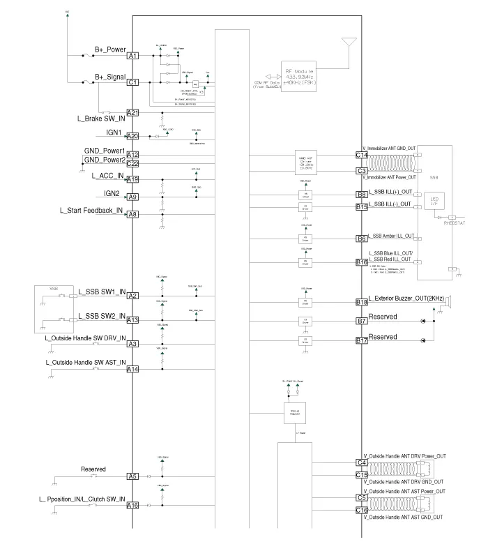
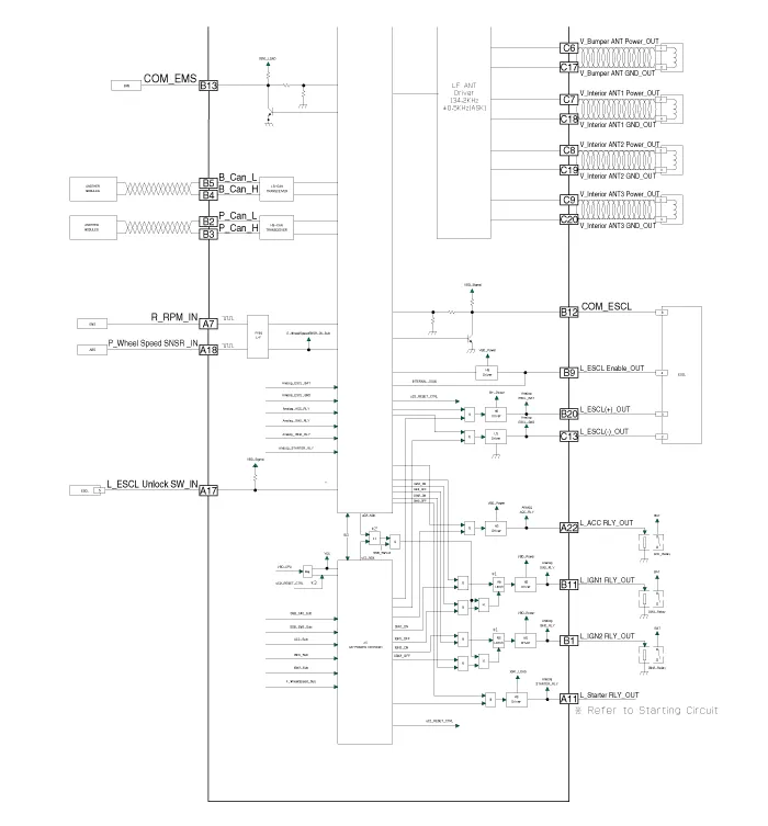
Schematic diagrams
| Circuit Diagram |
Repair procedures
| Removal |
Put on gloves to prevent hand injuries. |

|

Smart Key Unit
| 1. |
Disconnect the negative (-) battery terminal. |
| 2. |
Remove the glove box. (Refer to Body - "Glove Box") |
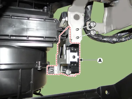
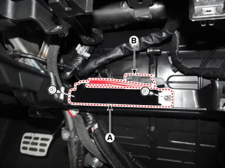
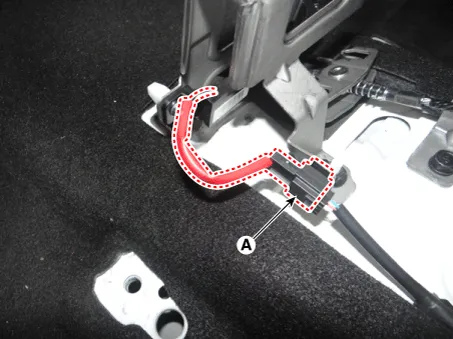
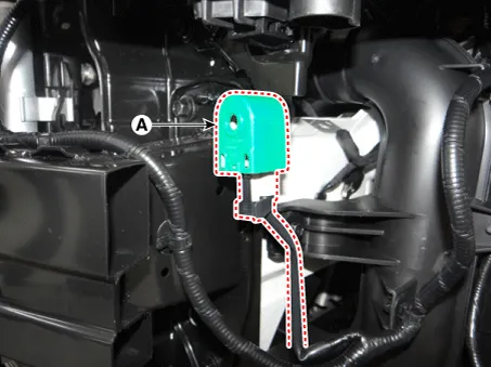
| 3. |
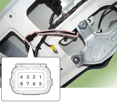
Remove the smart key unit (B) after disconnecting the connectors (A).
|

| 4. |
Remove the smart key unit (A) after loosening the mounting nuts.
|
Interior 1 Antenna
| 1. |
Disconnect the negative (-) battery terminal. |
| 2. |
Remove the heater and A/C controll unit. (Refer to Heating,Ventilation, Air Conditioning - "Heater & A/C Control Unit (Manual)") (Refer to Heating, Ventilation, Air conditioning - "Heater & A/C Control Unit (FATC)") |
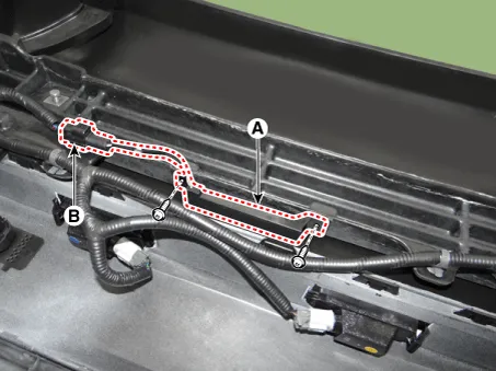
| 3. |
Remove the interior 1 antenna (A) after loosening the mounting screws and disconnecting the connector (B).
|
Interior 2 Antenna
| 1. |
Disconnect the negative (-) battery terminal. |
| 2. |
Remove the floor console assembly. (Reger to Body - "Floor Console Assembly") |
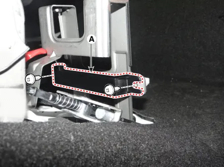
| 3. |
Disconnect the interior 2 antenna connector (A).
|
| 4. |
Remove the interior 2 antenna (A) after loosening the mounting screws.
|
Tailgate Antenna
| 1. |
Disconnect the negative (-) battery terminal. |
| 2. |
Remove the rear transverse trim. (Reger to Body - " Rear Transverse Trim") |
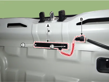
| 3. |
Remove the tailgate antenna (A) after loosening the mounting nuts and disconnecting the connector (B).
|
Rear Bumper Antenna
| 1. |
Disconnect the negative (-) battery terminal. |
| 2. |
Remove the rear bumper assembly. (Refer to Body - "Rear Bumper Assembly") |
| 3. |
Remove the rear bumper antenna (A) after loosening the mounting screws and disconnecting the connector (B).
|
Buzzer
| 1. |
Disconnect the negative (-) battery terminal. |
| 2. |
Remove the front bumper assembly. (Refer to Body - "Front Bumper Assembly") |
| 3. |
Remove the buzzer (A) after disconnecting the connector.
|
Door Outside Handle
| 1. |
Disconnect the negative (-) battery terminal. |
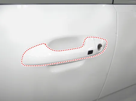
| 2. |
Remove the front door outside handle. (Refer to Body - "Front Door Outside Handle")
|

Tailgate Open Switch
| 1. |
Disconnect the negative (-) battery terminal. |
| 2. |
Remove the back view camera assembly. (Refer to Body Electrical System - "Back View Camera System") |
| 3. |
Remove the tailgate open switch assembly (A) after loosening the mounting screws.
|

| Inspection |
Smart Key Unit
(Refer to Smart Key System - "Smart Key Diagnostic")
Smart Key Switch
(Refer to Smart Key System - "Smart Key Diagnostic")
Antenna
(Refer to Smart Key System - "Smart Key Diagnostic")
Door Outside Handle
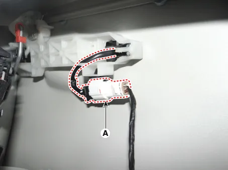
| 1. |
Disconnect the front door outside handle connector (A).
|
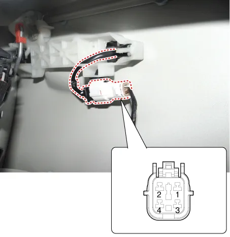
| 2. |
Check for continuity between terminals No 2 and No 4.
|
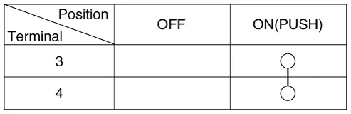
Tailgate Open Switch
| 1. |
Check for continuity between the tailgate open switch terminals.
|
| 2. |
If continuity is not specified, inspect the switch
|
| Installation |
Smart Key Unit
| 1. |
Install the smart key unit after connecting the connectors. |
| 2. |
Install the glove box. |
| 3. |
Connect the negative (-) battery terminal and check the smart key system. |
Interior 1 Antenna
| 1. |
Install the interior 1 antenna. |
| 2. |
Install the heater and A/C controll unit. |
| 3. |
Install the negative (-) battery terminal and check the smart key system. |
Interior 2 Antenna
| 1. |
Install the interior 2 antenna. |
| 2. |
Install the floor console assembly. |
| 3. |
Connect the negative (-) battery terminal and check the smart key system. |
Tailgate Antenna
| 1. |
Install the tailgate antenna. |
| 2. |
Install the rear transverse trim. |
| 3. |
Connect the negative (-) battery terminal and check the smart key system. |
Rear Bumper Antenna
| 1. |
Install the rear bumper antenna. |
| 2. |
Install the rear bumper assembly. |
| 3. |
Connect the negative (-) battery terminal and check the smart key system. |
Buzzer
| 1. |
Install the buzzer. |
| 2. |
Install the front bumper assembly. |
| 3. |
Connect the negative (-) battery terminal and check the smart key system. |
Door Outside Handle
| 1. |
Install the front door outside handle. |
| 2. |
Connect the negative (-) battery terminal and check the smart key system. |
Tailgate Open Switch
| 1. |
Install the tailgate open switch assembly. |
| 2. |
Install the back view camera assembly. |
| 3. |
Install the tailgate outside handle assembly. |
| 4. |
Connect the tailgate outside handle assembly connector. |
| 5. |
Install the tailgate trim. |
| 6. |
Install the negative (-) battery terminal and check the smart key system. |
Repair procedures Smart Key Smart Key Code Saving 1. Connect the DLC cable of KDS/GDS to the data link connector (16 pins) in driver side crash pad lower panel, turn the power on KDS/GDS.
Repair procedures Inspection Self Diagnosis With Scan Tool It will be able to diagnose defects of SMART KEY system with KDS/GDS quickly.
Other information:
Kia Rio 2017-2023 YB Service Manual: Turn Signal Lamp
Repair procedures Removal Door Mirror Turn Signal Lamp 1. Disconnect the negative (-) battery terminal. 2. Remove the mirror (A) from the mirror holder. Be careful not to damag
Kia Rio 2017-2023 YB Service Manual: Blower Unit
Components and components location Component Location Components 1. Intake actuator 2. Air filter 3. Air filter cover 4. Resistor 5. Mosfet 6. Intake seal 7. Intake upper cover 8.
Categories
- Manuals Home
- Kia Rio Owners Manual
- Kia Rio Service Manual
- Maintenance
- Engine Control / Fuel System
- Engine Mechanical System
- New on site
- Most important about car
