Kia Rio: Body Electrical System / Horn
Components and components location
| Component Location |
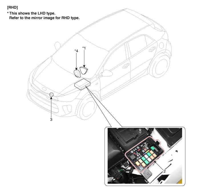
| 1. Horn switch 2. Horn relay |
3. Horn 4. Clock spring |
Repair procedures
| Removal |
| 1. |
Remove the front bumper assembly. (Refer to Body - "Front Bumper Assembly") |
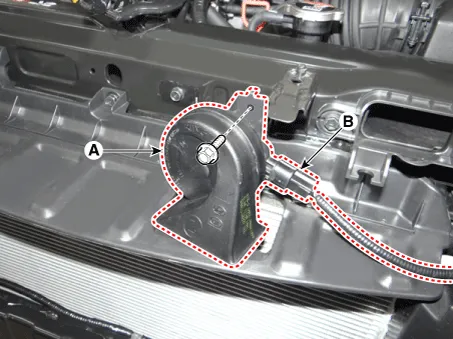
| 2. |
Remove the horn (A) after disconnecting the horn connector (B) and loosening the mounting the bolt.
|
| Installation |
| 1. |
Install the horn after connecting the horn connector. |
| 2. |
Install the front bumper assembly. |
| Inspection |
| 1. |
The relay on the horn of this vehicle is built into the engine room relay block. |
Components and components location Components Repair procedures Removal 1. Disconnect the negative (-) battery terminal.
Repair procedures Inspection 1. Disconnect the key warning switch connector (A) and ignition switch connector (B) from the steering column.
Other information:
Kia Rio 2017-2023 YB Service Manual: Receiver-Drier
Repair procedures Replacement 1. Remove the condenser. 2. Remove the cap (B) on the bottom of the condenser with L wrench (A). Tightening torque : 2.7~3.2 N.m (0.28~0.
Kia Rio 2017-2023 YB Service Manual: Cluster Ionizer (FATC only)
Description and operation Description The cluster ionizer helps to clean up odors in the vehicle or from the air-conditioner system. When the ignition switch ON, the inoizer runs a "CLEAN" mode and then a "ION" mode, switching every about 15 minutes.
Categories
- Manuals Home
- Kia Rio Owners Manual
- Kia Rio Service Manual
- Emission Control System
- Coolant
- Brake System
- New on site
- Most important about car
