Kia Rio: Emission Control System
Specifications
| Specifications |
Purge control solenoid valve (PCSV)
▷ Specification
|
Item |
Specification |
|
Coil resistance (Ω) |
18.5 - 22.5 [23°C(73.40°F)] |
| Tightening Torques |
|
Item |
kgf·m |
N·m |
lb·ft |
|
Positive Crankcase Ventilation (PCS) Valve |
0.19 - 0.29 |
1.89 - 2.84 |
1.40 - 2.09 |
|
Purge Control Solenoid Valve (PCSV) bracket mounting bolt |
1.0 - 1.2 |
9.8 - 11.8 |
7.2 - 8.7 |
Components and components location
| Components Location |
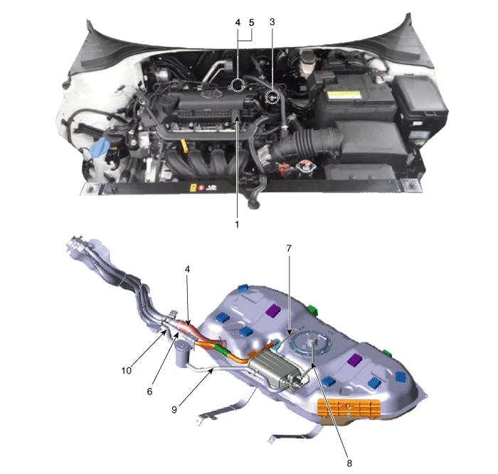
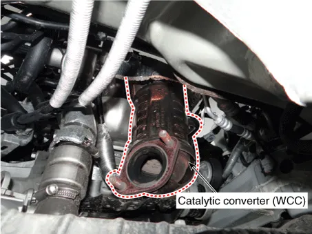
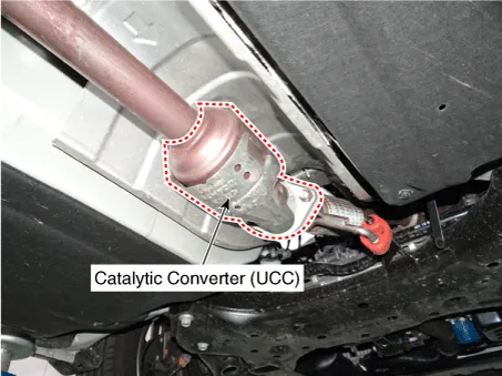
| 1. PCV valve 2. Canister 3. Purge control solenoid valve (PCSV) 4. Catalytic converter (WCC) 5. Catalytic converter (UCC) |
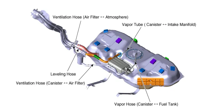
6. Leveling Hose 7. Vapor Tube (Canister ↔ Intake Manifold) 8. Vapor Hose (Canister ↔ Fuel Tank) 9. Ventilation Hose (Canister ↔ Air Filter) 10. Ventilation Hose (Air Filter ↔ Atmosphere) |
|
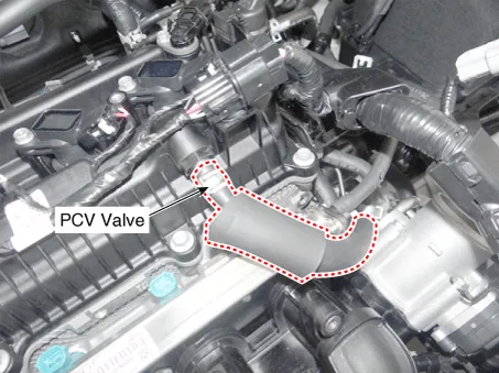
1. PCV valve |
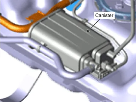
2. Canister |
|
|
|
|
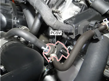
3. Purge Control Solenoid Valve (PCSV) |
4. Catalytic Converter (WCC) |
|
|
|
|
5. Catalytic Converter (UCC) |
|
|
|
|
|
6. Leveling Hose 7. Vapor Tube ( Canister ↔ Intake Manifold) 8. Vapor Hose (Canister ↔ Fuel Tank) 9. Ventilation Hose (Canister ↔ Air Filter) 10. Ventilation Hose (Air Filter ↔ Atmosphere) |
|
|
|
|
Description and operation
| Description |
Emissions control system consists of the three major systems.
| • |
Crankcase emission control system prevents blow-by gas from going into the atmosphere. This system burns these gases after moving them to the intake manifold (Closed Crankcase Ventilation Type). |
| • |
Evaporative emission control system prevents evaporative gas going into the atmosphere. This system burns the gases at appropriate engine operating condition after gathering it in the canister. |
| • |
Exhaust emission control system converts the three pollutants hydrocarbons (HC), carbon monoxide (CO), and oxides of nitrogen (NOx) into harmless substances by using the 3-way catalytic converter. |
Schematic diagrams
| Schematic Diagram |

Troubleshooting
| Troubleshooting |
|
Symptom |
Suspect area |
|
Engine will not start or hard to start |
Vapor hose damaged or disconnected |
|
Engine hard to start |
Malfunction of the purge control solenoid valve |
|
Rough idle or engine stalls |
Vapor hose damaged or disconnected |
|
Malfunction of the PCV valve |
|
|
Rough idle |
Malfunction of the evaporative emission control system |
|
Excessive oil consumption |
Positive crankcase ventilation line clogged |
Components and components location Components 1. Left Remote Control Switch (Audio + Hands free + Voice) 2. Right Remote Control Switch (Cruise+Trip Computer) Schematic diagrams Circuit Diagram [Audio] [Audio + Bluetooth] [Audio + Bluetooth + Voice] [Trip] [Trip + ACC (2 Button)] [Trip + ACC + SLD (2 Button)] [Trip + ACC (4 Button)] [Trip + ACC + SLD (4 Button)] Repair procedures Removal 1.
Schematic diagrams Schematic Diagram Repair procedures Inspection 1. After disconnecting the vapor hose from the PCV valve, remove the PCV valve.
Other information:
Kia Rio 2017-2023 YB Service Manual: Front Washer Motor
Repair procedures Inspection Front Washer Motor 1. With the washer motor connected to the reservoir tank, fill the reservoir tank with water. • Before filling the reservoir tank wi
Kia Rio 2017-2023 YB Service Manual: Condenser
Repair procedures Inspection 1. Check the condenser fins for clogging and damage. If clogged, clean them with water, and blow them with compressed air. If bent, gently bend them using a screwdriver or pliers. 2.
Categories
- Manuals Home
- Kia Rio Owners Manual
- Kia Rio Service Manual
- Clutch System
- General Information
- Coolant
- New on site
- Most important about car
