Kia Rio: Crankcase Emission Control System / Positive Crankcase Ventilation (PCV) Valve
Description and operation
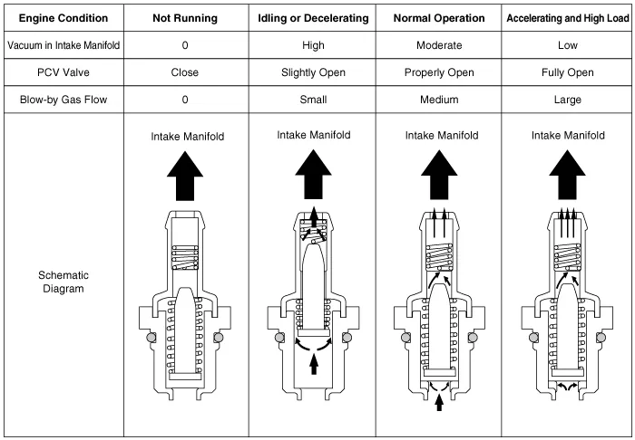
| Operation Principle |
Repair procedures
| Removal |
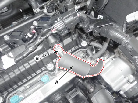
| 1. |
Disconnect the vapor hose (A) and then remove the PCV valve (B).
|
| Inspection |
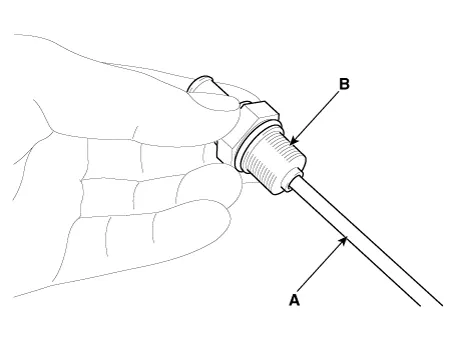
| 1. |
Insert a thin stick (A) into the PCV valve (B) from the threaded side to check that the plunger moves.
|

| Installation |
| 1. |
Install in the reverse order of removal.
|
Schematic diagrams Schematic Diagram Repair procedures Inspection 1. After disconnecting the vapor hose from the PCV valve, remove the PCV valve.
Description and operation Description Evaporative Emission Control System prevents fuel vapor stored in fuel tank from vaporizing into the atmosphere.
Other information:
Kia Rio 2017-2023 YB Service Manual: Sunroof Switch
Components and components location Components Repair procedures Inspection 1. Disconnect the negative (-) battery terminal. 2. Open the sunglass case cover from the overhead console and remove the 2 screws holding the overhead console.
Kia Rio 2017-2023 YB Service Manual: Temperature Control Actuator
Description and operation Description The heater unit includes mode control actuator and temperature control actuator. The temperature control actuator is located at the heater unit. It regulates the temperature by the procedure as follows.
Categories
- Manuals Home
- Kia Rio Owners Manual
- Kia Rio Service Manual
- Brake System
- Timing Chain
- Engine Electrical System
- New on site
- Most important about car
