
Kia Rio: Sunroof / Sunroof Switch
Components and components location
| Components |

Repair procedures
| Inspection |
| 1. |
Disconnect the negative (-) battery terminal. |
| 2. |
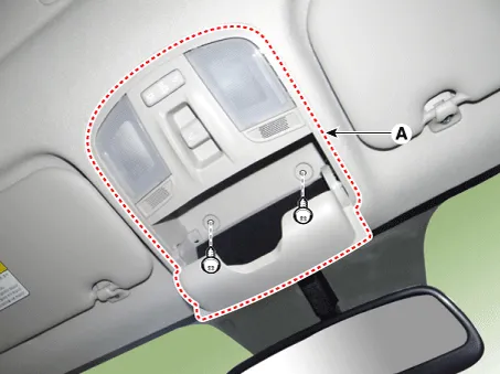
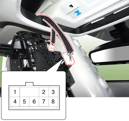
Open the sunglass case cover from the overhead console and remove the 2 screws holding the overhead console. Disconnect the switch connector and Map lamp connector, and then remove the overhead console lamp (A).
|
| 3. |
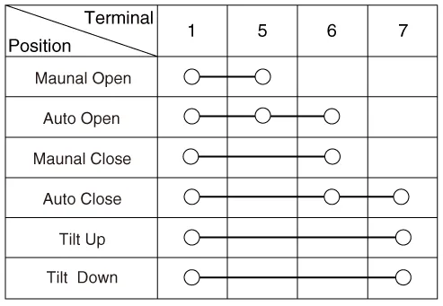
Check for continuity between the terminals. If the continuity is not shown as specified, replace the panoramaroof switch.
|
| Removal |
| 1. |
Disconnect the negative (-) battery terminal. |
| 2. |
Remove the overhead console lamp. (Refer to Lighting System - "Overhead Console Lamp") |
| 3. |
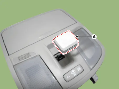
Remove the sunroof switch knob (A).
|
| 4. |
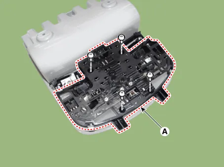
Remove the sunroof bulb base (A) after loosening the mounting screws.
|
| 5. |
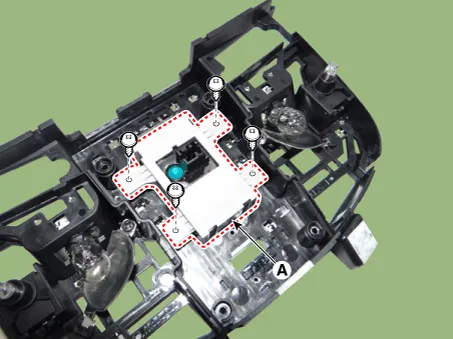
Remove the sunroof switch assembly (A) after loosening the mounting screws.
|
| Installation |
| 1. |
Install the sunroof switch assembly. |
| 2. |
Install the sunroof bulb base. |
| 3. |
Install the sunroof switch knob. |
| 4. |
Install the overhead console lamp. |
| 5. |
Connect the negative (-) battery terminal. |
Components and components location Component Location 1. Sunroof 2. Sunroof switch 3. Sunroof motor & controller Schematic diagrams Circuit Diagram
Repair procedures Inspection 1. Disconnect the negative (-) battery terminal. 2. Remove the roof trim assembly.
Other information:
Kia Rio 2017-2023 YB Service Manual: Parking Assist Sensor
Components and components location Components Repair procedures Removal 1. Disconnect the negative (-) battery terminal. 2. Remove the rear bumper assembly. (Refer to Body - "Rear Bumper Assembly") 3.
Kia Rio 2017-2023 YB Service Manual: Power Mosfet (FATC)
Repair procedures Inspection 1. Turn the ignition switch ON. 2. Manually operate the control switch and measure the voltage of blower motor. 3. Select the control switch to raise voltage until high speed.
Categories
- Manuals Home
- Kia Rio Owners Manual
- Kia Rio Service Manual
- Filler-Neck Assembly
- Engine Electrical System
- Maintenance
- New on site
- Most important about car
