Kia Rio: Steering System
Specifications
| Specification |
|
Item |
Specification |
|
|
Type |
Motor Driven Power Steering |
|
|
Steering gear |
Type |
Rack & Pinion |
|
Rack stroke |
150 ± 1 mm (5.9055 ± 0.0394 in) |
|
|
Steering angle(Max.) |
Inner |
39.5° (+ 0.5° -1.5°) |
|
Outer |
32.6° |
|
Tightening Torques
|
Item |
Tightening torque (kgf·m) |
||
|
N·m |
kgf·m |
lb·ft |
|
|
Tire wheel hub nuts |
107.9 - 127.5 |
11.0 - 13.0 |
79.6 - 94.0 |
|
Steering wheel lock nut |
44.1 - 49.0 |
4.5 - 5.0 |
32.5 - 36.2 |
|
Steering column mounting nut |
24.5 - 29.4 |
2.5 - 3.0 |
18.1 - 21.7 |
|
Steering column mounting bolt |
53.9 - 58.8 |
5.5 - 6.0 |
39.8 - 43.4 |
|
Universal joint to pinion of steering gear |
32.4 - 37.3 |
3.3 - 3.8 |
23.9 - 27.5 |
|
Tie rod end ball joint nut |
22.6 - 33.3 |
2.3 - 3.4 |
16.6 - 24.5 |
|
Lower arm ball joint bolt and nut |
58.8 - 70.6 |
6.0 - 7.2 |
43.4 - 52.1 |
|
Steering gear box mounting bolts |
88.3 - 107.9 |
9.0 - 11.0 |
65.1 - 79.6 |
|
Stabilizer link nut |
98.1 - 117.7 |
10.0 - 12.0 |
72.3 - 86.8 |
|
Sub frame mounting bolts & nuts |
176.5 - 196.1 |
18.0 - 20.0 |
130.2 - 144.7 |
Special service tools
| Special Service Tools |
|
Tool Name / Number |
Illustration |
Description |
|
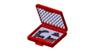
Lower arm ball joint remover 0K545-A9100 |
|
Used for removal of front lower arm from front axle |
|
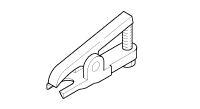
Ball joint remover 09568-2J100 |
|
Used for removal of ball joint |
Repair procedures
| Service Adjustment Procedure |
| Steering Wheel Play Inspection |
| 1. |
Turn the steering wheel so that the front wheels are facing straight ahead. |
| 2. |
Measure the distance that the steering wheel can be turned without moving the front wheels.
|
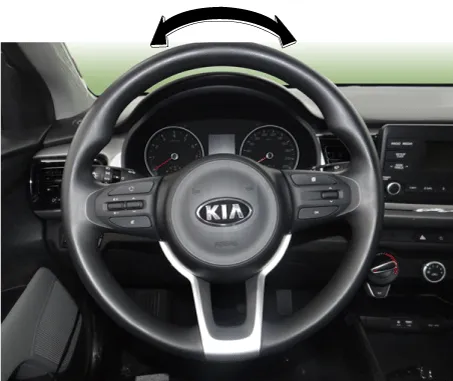
| 3. |
If the play exceeds standard value, inspect the steering column, shaft, and linkages |
| Checking Stationary Steering Effort |
| 1. |
Position the vehicle on a level surface and place the steering wheel in the straight ahead position. |
| 2. |
Start the engine and turn the steering wheel from lock to lock several times to warm up the power steering fluid. |
| 3. |
Attach a spring scale to the steering wheel. With the idle RPM, pull the scale and read it as soon as the tires begin to turn.
|
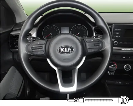
| 4. |
If the measured value exceeds standard value, inspect the steering gear box. |
Troubleshooting
| Troubleshooting |
|
Symptom |
Probable cause |
Remedy |
|
Play in steering |
Loose yoke plug |
Retighten |
|
Loose steering gear mounting bolts |
Retighten |
|
|
Loose or worn tie rod end |
Retighten or replace as necessary |
|
|
Steering wheel does not return properly |
Excessive turning resistance of tie rod end |
Replace |
|
Yoke plug excessively tight |
Adjust |
|
|
Tie rod and/or ball joint not turning smoothly |
Replace |
|
|
Loose mounting of gear box mounting bracket and/or worn steering shaft joint
|
Retighten |
|
|
Worn steering shaft joint and/or body grommet |
Correct or replace |
|
|
Distorted rack |
Replace |
|
|
Damaged pinion bearing |
Replace |
|
|
Rattling or chucking noise in the rack and pinion |
Interference with hoses from vehicle body |
Reposition |
|
Loose gear box bracket |
Retighten |
|
|
Loose tie rod end and/or ball joint |
Retighten |
|
|
Worn tie rod and/or ball joint |
Replace |
|
|
Noise in the oil pump |
Low fluid level |
Replenish |
|
Air in the fluid |
Bleed air |
|
|
Loose pump mounting bolts |
Retighten |
Components and components location Components 1. HECU 2. Cluster 3. TPMS SET Switch 4. Wheel speed sensor 5.
Description and operation Description MDPS (Motor Driven Power Steering) system uses an electric motor to assist the steering force and it is an engine operation independent steering system.
Other information:
Kia Rio 2017-2023 YB Service Manual: Hazard Lamp Switch
Repair procedures Inspection 1. Check for continuity between terminals. If the continuity is not as specified, replace the hazard lamp switch. No. Description No.
Kia Rio 2017-2023 YB Service Manual: Rear Combination Lamp
Repair procedures Removal Rear Combination Lamp (Outside) 1. Disconnect the negative (-) battery terminal. 2. Remove the rear combination lamp (A) after loosening the mounting screws. 3.
Categories
- Manuals Home
- Kia Rio Owners Manual
- Kia Rio Service Manual
- Engine Mechanical System
- Suspension System
- Filler-Neck Assembly
- New on site
- Most important about car
