Kia Rio: Lighting System / Vanity Lamp
Repair procedures
| Removal |
| 1. |
Disconnect the negative (-) battery terminal. |
| 2. |
Detach the vanity lamp (A) using a flat-tip screwdriver.
|
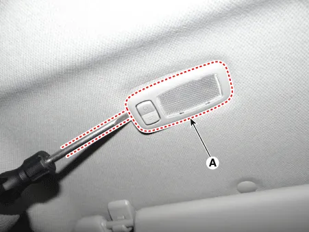
| 3. |
Disconnect the vanity lamp connector (A).
|

Bulb Replacement
| 1. |
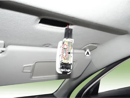
Detach the vanity lamp (A) using a flat-tip screwdriver.
|
| 2. |
Remove the vanity lamp bulb (A).
|
| Installation |
| 1. |
Connect the vanity lamp connector. |
| 2. |
Install the vanity lamp. |
| 3. |
Connect the negative (-) battery terminal. |
Repair procedures Removal • Put on gloves to prevent hand injuries.
Repair procedures Inspection 1. Remove the overhead console lamp assembly then check for continuity between terminals.
Other information:
Kia Rio 2017-2023 YB Service Manual: Overhead Console Lamp
Repair procedures Inspection 1. Remove the overhead console lamp assembly then check for continuity between terminals. If the continuity is not as specified, replace the map lamp switch. Removal 1.
Kia Rio 2017-2023 YB Service Manual: Power Door Locks
Components and components location Component Location 1. Driver power window switch 2. Assist power window switch 3 . Body Comtrol Module (BCM) 4 . Tailgate actuator 5 . Door latch lock actuator 6 .
Categories
- Manuals Home
- Kia Rio Owners Manual
- Kia Rio Service Manual
- Timing Chain
- Maintenance Schedule
- Clutch System
- New on site
- Most important about car
