Kia Rio: Lighting System / Overhead Console Lamp
Repair procedures
| Inspection |
| 1. |
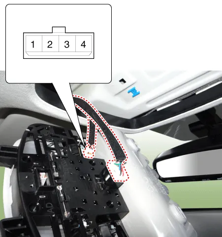
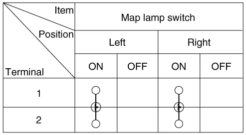
Remove the overhead console lamp assembly then check for continuity between terminals. If the continuity is not as specified, replace the map lamp switch.
|
| Removal |
| 1. |
Disconnect the negative (-) battery terminal. |
| 2. |
Remove the two mounting screws. And then remove the overhead console (A).
|

| 3. |
Remove the overhead console after disconnecting the connectors (A).
|

| Installation |
| 1. |
Install the overhead console lamp after connecting the connector. |
| 2. |
Install the lens after tightening 2 screws. |
Repair procedures Removal 1. Disconnect the negative (-) battery terminal. 2. Detach the vanity lamp (A) using a flat-tip screwdriver.
Repair procedures Inspection 1. Check for continuity between terminals. If the continuity is not as specified, replace the hazard lamp switch.
Other information:
Kia Rio 2017-2023 YB Service Manual: Photo Sensor (FATC only)
Description and operation Description The photo sensor is located at the center of defrost nozzles. The photo sensor contains a photovoltaic (sensitive to sunlight) diode. The solar radiation received by its light receiving portion, generates an electromotive force in proportion to the amount of radiation received which is tran
Kia Rio 2017-2023 YB Service Manual: Blower Resistor (MANUAL)
Repair procedures Inspection 1. Measure the resistance between the terminals. 2. The measured resistance is not within specification, the blower resistor must be replaced. (After removing the resistor) Replacement 1.
Categories
- Manuals Home
- Kia Rio Owners Manual
- Kia Rio Service Manual
- Clutch System
- Engine Oil and Filter
- Maintenance Schedule
- New on site
- Most important about car
