
Kia Rio: Blower / Blower Resistor (MANUAL)
Repair procedures
| Inspection |
| 1. |
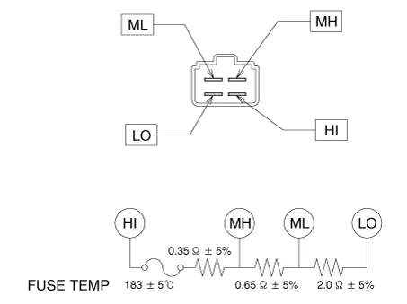
Measure the resistance between the terminals. |
| 2. |
The measured resistance is not within specification, the blower resistor must be replaced. (After removing the resistor)
|
| Replacement |
| 1. |
Disconnect the negative (-) battery terminal. |
| 2. |
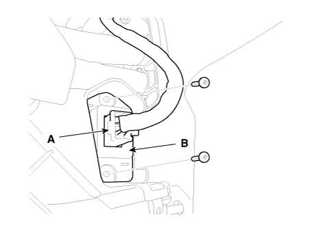
Disconnect the connector (A) and then remove the blower resistor (B) after loosening the mounting screws.
|
| 3. |
Installation is the reverse order of removal. |
Repair procedures Inspection 1. Connect the battery voltage and check the blower motor rotation. 2.
Repair procedures Inspection 1. Turn the ignition switch ON. 2. Manually operate the control switch and measure the voltage of blower motor.
Other information:
Kia Rio 2017-2023 YB Service Manual: Power Window Motor
Components and components location Components [Standard window motor] [Safety window motor] Repair procedures Inspection • When removing with a flat-tip screwdriver or remover, wrap protective
Kia Rio 2017-2023 YB Service Manual: Windshield Wiper-Washer Switch
Repair procedures Removal [BCM Type] 1. Disconnect the negative (-) battery terminal. 2. Remove the steering wheel. (Refer to Steering System - "Steering Wheel") 3.
Categories
- Manuals Home
- Kia Rio Owners Manual
- Kia Rio Service Manual
- Engine Mechanical System
- Body Electrical System
- Suspension System
- New on site
- Most important about car
