Kia Rio: Windshield Wiper/Washer / Windshield Wiper-Washer Switch
Repair procedures
| Removal |
| [BCM Type] |
| 1. |
Disconnect the negative (-) battery terminal. |
| 2. |
Remove the steering wheel. (Refer to Steering System - "Steering Wheel") |
| 3. |
Remove the steering column upper and lower shrouds after loosening the screws. (Refer to Body - "Steering Column Shroud Panel") |
| 4. |
Remove the clock spring. (Refer to Restraint - "Driver Airbag (DAB) Module and Clock Spring")
|
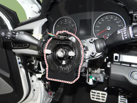
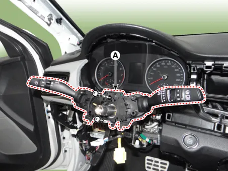
| 5. |
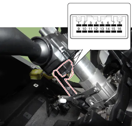
Disconnect the multifunction switch connector (A).
|
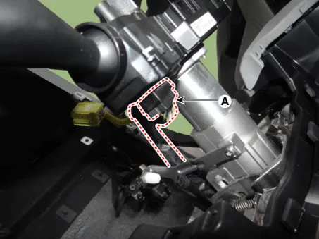
| 6. |
Remove the multifunction switch assembly (A) after loosening the mounting screws.
|
| [Non-BCM Type] |
| 1. |
Disconnect the negative (-) battery terminal. |
| 2. |
Remove the steering column upper and lower shrouds after loosening the screws. (Refer to Body - "Steering Column Shroud Panal") |
| 3. |
Disconnect the wiper switch / washer switch connector (A).
|

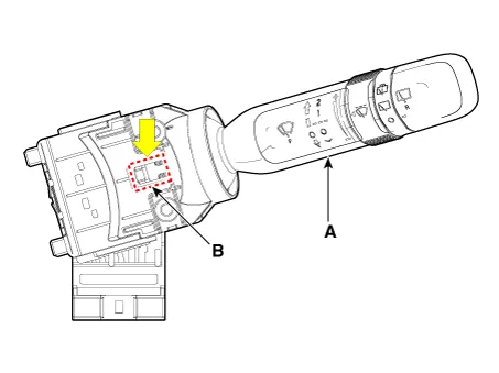
| 4. |
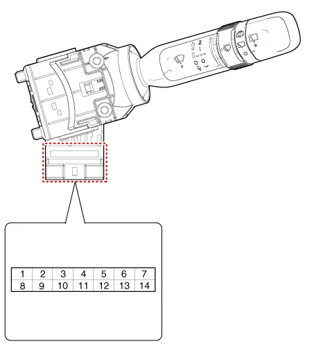
Remove the wiper switch / washer switch (A) by pushing the lock pin (B).
|
| Installation |
| [BCM Type] |
| 1. |
Install the multifunction switch. |
| 2. |
Install the clock spring. |
| 3. |
Install the steering column upper and lower shrouds. |
| 4. |
Install the steering wheel. |
| 5. |
Connect the negative (-) battery terminal. |
| [Non-BCM Type] |
| 1. |
Install the wiper switch / washer switch. |
| 2. |
Connect the wiper switch / washer switch connector. |
| 3. |
Install the steering column upper and lower shrouds. |
| 4. |
Connect the negative (-) battery terminal. |
| Inspection |
Multifunction Switch Inspection
| [BCM Type] |
| 1. |
Check for continuity between the terminals in each switch position as shown below.
[Left Handle Drive]
[Right Handle Drive]
|
Inspection (With KDS/GDS)
| 1. |
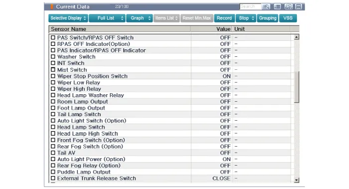
In the body electrical system, failure can be quickly diagnosed by using the vehicle diagnostic system (KDS/GDS). The diagnostic system(KDS/GDS) provides the following information.
|
| 2. |
Select the 'Car model' and the 'Body Control Module (BCM)' to be checked in order to check the vehicle with the tester. |
| 3. |
Select the 'Current Data' menu to search the current state of the input/output data.
|
| [Non-BCM Type] |
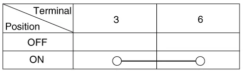
| 1. |
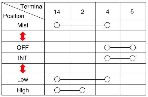
Check for continuity between the terminals in each switch position as shown below.
Front Wiper & Washer Switch [LHD]
[RHD]
Front Washer Switch [LHD]
[RHD]
|


Components and components location Component Location 1. Windshield wiper arm & blade 2. Wiper & washer switch 3.
Components and components location Component Location 1. Cap 2. Nut 3. Wiper arm & blade 4. Cowl top cover 5.
Other information:
Kia Rio 2017-2023 YB Service Manual: PTC Heater
Description and operation Description The PTC (Positive Temperature Coefficient) heater is installed at the exit or the backside of heater core. The PTC heater is an electric heater using a PTC element as an auxiliary heating device that supplements deficiency of interior heat source in highly effective diesel engine.
Kia Rio 2017-2023 YB Service Manual: Heater & A/C Control Unit (MANUAL)
Components and components location Components Connector pin function NO. Connector A Connector B 1 Low Battery 2 Common ISG Battery 3 High Illumination (+)
Categories
- Manuals Home
- Kia Rio Owners Manual
- Kia Rio Service Manual
- Engine Electrical System
- Motor Driven Power Steering
- Engine Control / Fuel System
- New on site
- Most important about car
