Kia Rio: Windshield Wiper/Washer / Front Wiper Motor
Components and components location
| Component Location |
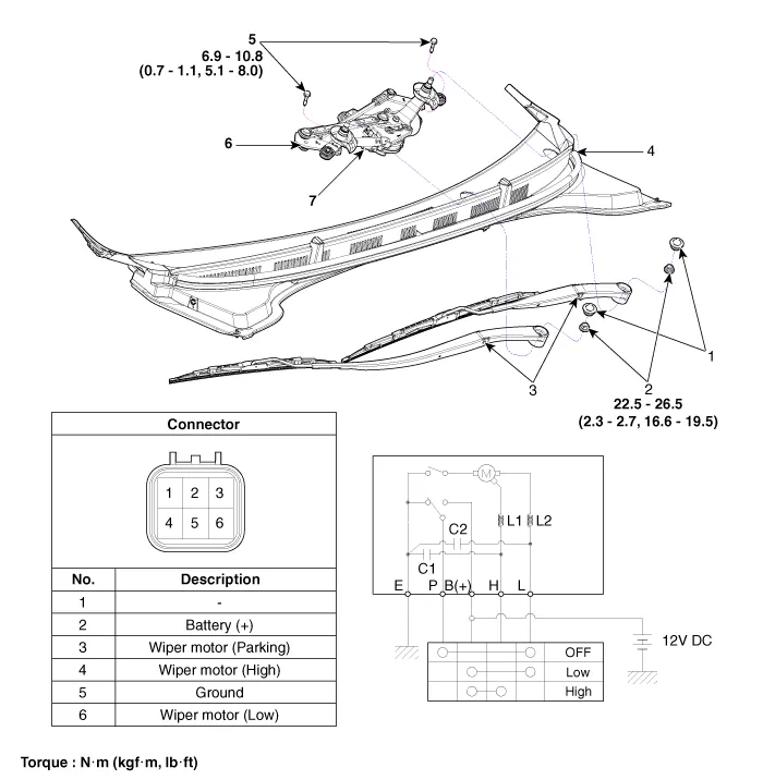
| 1. Cap 2. Nut 3. Wiper arm & blade 4. Cowl top cover |
5. Bolt 6. Wiper motor & linkage assembly 7. Wiper motor connector |
Repair procedures
| Removal |
| 1. |
Disconnect the negative (-) battery terminal. |
| 2. |
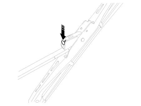
If necessary, release the wiper blade fixing clip by pulling it up and remove the wiper blade from the inside radius of wiper arm.
|
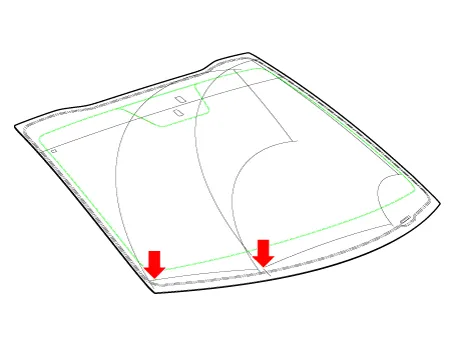
| 3. |
Remove the cowl top cover. (Refer to Body - "Cowl Top Cover") |
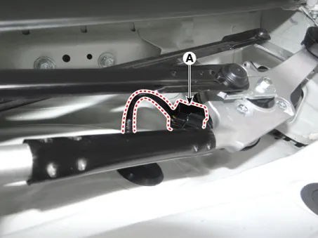
| 4. |
Disconnect the wiper motor connector (A).
|
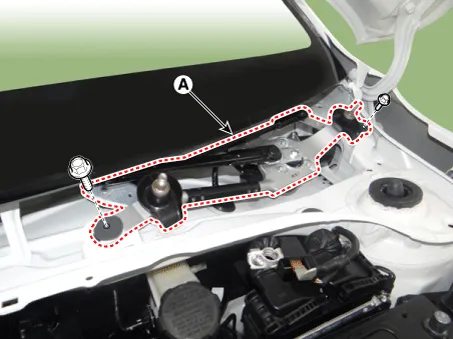
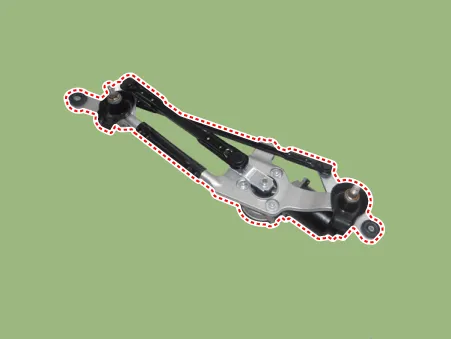
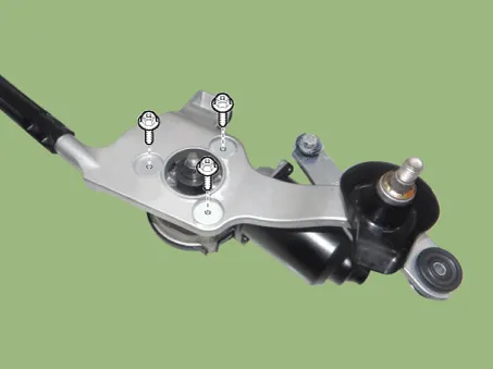
| 5. |
Remove the wiper motor & linkage assembly (A) after loosening the mounting bolts.
|
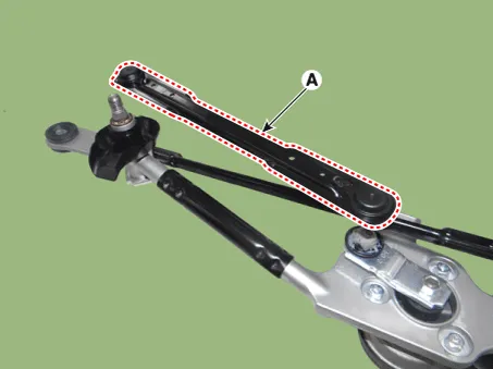
| 6. |
Hold the wiper motor crank arm and remove the upper linkage (A).
|

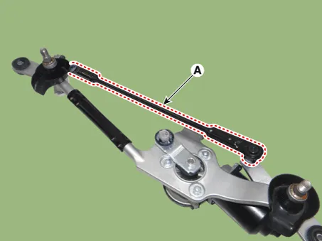
| 7. |
Remove the lower linkage (A) from the wiper motor crank arm.
|
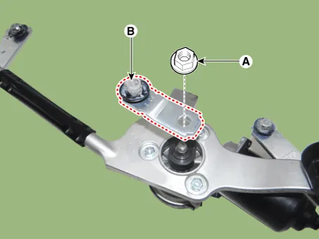
| 8. |
Remove the crank arm (B) after loosening a nut (A).
|
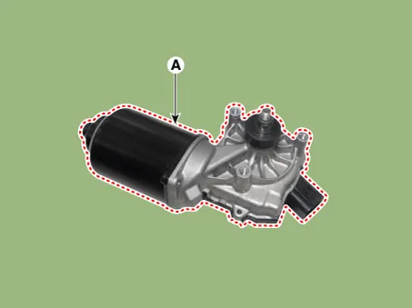
| 9. |
Remove the wiper motor (A) after loosening the mounting bolts.
|
| Installation |
| 1. |
Install the wiper motor. |
| 2. |
Install the crank arm.
|
| 3. |
Install the lower and upper linkage to the wiper motor crank arm. |
| 4. |
Install the wiper motor and linkage assembly and then connect the wiper motor connector.
|
| 5. |
Install the cowl top cover. |
| 6. |
Install the windshield wiper arm and blade.
|

| 7. |
Install the wiper arm and blade to the specified position. Auto stop position (Blade)
|
| Inspection |
| 1. |
Remove the connector from the wiper motor.
|
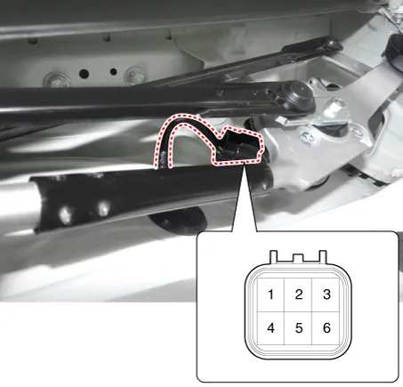
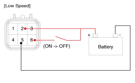
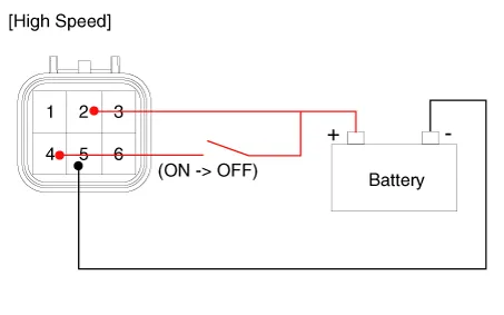
| 2. |
Attach the positive (+) lead from the battery to terminal 2 and the negative (-) lead to terminal 5.
|
| Inspection (With KDS/GDS) |
| 1. |
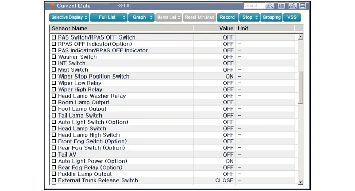
In the body electrical system, failure can be quickly diagnosed by using the vehicle diagnostic system (KDS/GDS). The diagnostic system(KDS/GDS) provides the following information.
|
| 2. |
Select the 'Car model' and the 'Body Control Module (BCM)' to be checked in order to check the vehicle with the tester. |
| 3. |
Select the 'Current Data' menu to search the current state of the input/output data.
|
Repair procedures Removal [BCM Type] 1. Disconnect the negative (-) battery terminal. 2. Remove the steering wheel.
Repair procedures Inspection Front Washer Motor 1. With the washer motor connected to the reservoir tank, fill the reservoir tank with water.
Other information:
Kia Rio 2017-2023 YB Service Manual: Sunroof
C
Kia Rio 2017-2023 YB Service Manual: Compressor Oil
Repair procedures Oil Specification 1. The HFC-134a system requires synthetic compressor oil (PAG) whereas the R-12 system requires mineral compressor oil. The two oils must never be mixed. 2. Compressor oil (PAG) varies according to compressor model.
Categories
- Manuals Home
- Kia Rio Owners Manual
- Kia Rio Service Manual
- Coolant
- Maintenance
- Timing Chain
- New on site
- Most important about car
