Kia Rio: Windshield Wiper/Washer / Front Washer Motor
Repair procedures
| Inspection |
Front Washer Motor
| 1. |
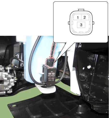
With the washer motor connected to the reservoir tank, fill the reservoir tank with water.
|

| 2. |
Connect positive (+) battery cables to terminal 1 and negative (-) battery cables to terminal 2 respectively. |
| 3. |
Check that the motor operates normally and the washer motor runs and water sprays from the front nozzles. |
| 4. |
If they are abnormal, replace the washer motor. [Front & Rear washer]
|
| Removal |
Front Washer Motor
| 1. |
Disconnect the negative (-) battery terminal. |
| 2. |
Remove the engine room under cover. D 1.4 U2 TCI (Refer to Engine Mechanical System - "Engine Room Under Cover") G 1.0 T-GDI KAPPA (Refer to Engine Mechanical System - "Engine Room Under Cover") G 1.2 MPI KAPPA (Refer to Engine Mechanical System - "Engine Room Under Cover") G 1.4 MPI KAPPA (Refer to Engine Mechanical System - "Engine Room Under Cover") |
| 3. |
Remove the front wheel guard [RH]. (Refer to Body - "Front Wheel Guard") |
| 4. |
Drain the washer fluid to less than 650 cc. |
| 5. |
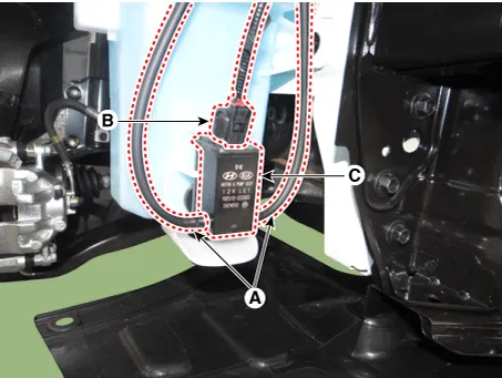
Disconnect the washer hose (A) and washer motor connector (B). |
| 6. |
Remove the front washer motor (C).
|
Reservoir Tank
| 1. |
Disconnect the negative (-) battery terminal. |
| 2. |
Remove the engine room under cover. D 1.4 U2 TCI (Refer to Engine Mechanical System - "Engine Room Under Cover") G 1.0 T-GDI KAPPA (Refer to Engine Mechanical System - "Engine Room Under Cover") G 1.2 MPI KAPPA (Refer to Engine Mechanical System - "Engine Room Under Cover") G 1.4 MPI KAPPA (Refer to Engine Mechanical System - "Engine Room Under Cover") |
| 3. |
Remove the front wheel guard [RH]. (Refer to Body - "Front Wheel Guard") |
| 4. |
Drain the washer fluid to less than 650 cc. |
| 5. |
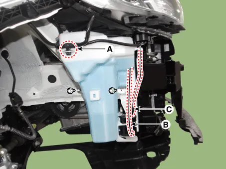
Remove the wiring mounting clip (A). |
| 6. |
Disconnect the washer hoses (B) and connector (C). |
| 7. |
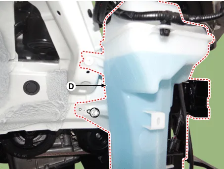
Remove the reservoir tank (D) after loosening the bolts.
|
| Installation |
Front Washer Motor
| 1. |
If necessary, clean the washer motor filter.
|
| 2. |
Install the front washer motor. |
| 3. |
Connect the front washer motor connector. |
| 4. |
Install the front wheel guard [RH]. |
| 5. |
Install the engine room under cover. |
| 6. |
Connect the negative (-) battery terminal. |
Reservoir Tank
| 1. |
If necessary, clean the washer motor filter.
|
| 2. |
Install the reservoir tank. |
| 3. |
Install the washer motor hose and connectors. |
| 4. |
Install the front wheel guard [RH]. |
| 5. |
Install the engine room under cover. |
| 6. |
Connect the negative (-) battery terminal. |
Components and components location Component Location 1. Cap 2. Nut 3. Wiper arm & blade 4. Cowl top cover 5.
Components and components location Components Schematic diagrams Circuit Diagram Description and operation Description Integrated Rain Sensor Integrated rain sensor (A) controls three systems: front wiper, auto-light, and central air conditioner.
Other information:
Kia Rio 2017-2023 YB Service Manual: Antenna Coil
Repair procedures Removal 1. Disconnect the negative (-) battery terminal. 2. Remove the crash pad lower panel. (Refer to Body - "Crash Pad Lower Panel") 3. Remove the steering column upper and lower shroud panel.
Kia Rio 2017-2023 YB Service Manual: Receiver-Drier
Repair procedures Replacement 1. Remove the condenser. 2. Remove the cap (B) on the bottom of the condenser with L wrench (A). Tightening torque : 2.7~3.2 N.m (0.28~0.
Categories
- Manuals Home
- Kia Rio Owners Manual
- Kia Rio Service Manual
- Engine Oil and Filter
- Coolant
- Motor Driven Power Steering
- New on site
- Most important about car
