Kia Rio: Engine Electrical System
Specifications
| Specification |
| Ignition System |
Ignition Coil
|
Item |
Specification |
|
Rated Voltage (V) |
12 |
|
Operation Voltage (V) |
5 - 16 |
|
Item |
Specification |
|||||
|
Engine Speed (RPM) |
1000 |
2000 |
3000 |
4000 |
5000 |
6000 |
|
Dwell Time (ms) |
3.82 |
2.61 |
2.27 |
1.93 |
1.79 |
1.6 |
|
Secondary Coil Voltage (kV) |
32 ↑ |
32 ↑ |
31 ↑ |
30 ↑ |
29 ↑ |
27 ↑ |
Spark plug
|
Item |
Specification |
|
Type |
SILKR6C10E |
|
Gap |
0.9 - 1.0 mm (0.0354 - 0.0394in.) |
|
Electrode Material |
Iridium |
Condenser
|
Item |
Specification |
|
Capacitance (uF) |
0.47 [1KHz] |
|
Insulation resistance (MΩ) |
1,000 [DC 500 V/1 Min] |
| Charging System |
Alternator
▷ 13.5V, 90A
|
Item |
Specification |
|
Rated voltage |
13.5V, 90A |
|
Speed in use |
1,000 - 18,000 rpm |
|
Voltage regulator |
IC Regulator built-in type |
|
Regulator Setting Voltage (Internal mode) |
14.55 ± 0.3V |
|
Connector |
3 Pin (C, FR, L) |
▷ 13.5V, 130A
|
Item |
Specification |
|
Rated voltage |
13.5V, 130A |
|
Speed in use |
1,000 - 18,000 rpm |
|
Voltage regulator |
IC Regulator built-in type |
|
Regulator Setting Voltage (Internal mode) |
14.55 ± 0.3V |
|
Connector |
3 Pin (C, FR, L) |
|
Pully Type |
OAP |
Battery
▷ AGM60L-DIN
|
Item |
Specification |
|
Capacity [20HR/5HR] (AH) |
60/48 |
|
Cold Cranking Amperage (A) |
640 (SAE) / 640(EN) |
|
Reserve Capacity (Min) |
100 |
|

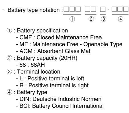
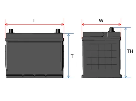
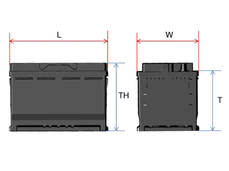
BCI Type
DIN Type
AGM DIN Type
|
| Starting System |
Starter
▷12V, 1.2kW : ISG only
|
Item |
Specification |
|
|
Rated voltage |
12 V, 1.2 kW |
|
|
The number of pinion teeth |
13 |
|
|
Performance [No-load, 11.5 V] |
Ampere |
Max. 117 A |
|
Speed |
Min. 3,200 rpm |
|
▷12V, 0.9kW : NON- ISG
|
Item |
Specification |
|
|
Rated voltage |
12 V, 0.9 kW |
|
|
The number of pinion teeth |
11 |
|
|
Performance [No-load, 11.5 V] |
Ampere |
Max. 85 A |
|
Speed |
Min. 3,300 rpm |
|
| Tightening Torques |
|
Item |
N·m |
kgf·m |
lb·ft |
|
Ignition coil mounting bolt |
9.8 - 11.8 |
1.0 - 1.2 |
7.2 - 8.7 |
|
Spark plug |
14.7 - 24.5 |
1.5 - 2.5 |
10.9 - 18.1 |
|
Condenser mounting nut / bolt |
9.8 - 11.8 |
1.0 - 1.2 |
7.2 - 8.7 |
|
Alternator upper mounting bolt |
19.6 - 26.5 |
2.0 - 2.7 |
14.5 - 19.5 |
|
Alternator lower mounting bolt |
29.4 - 41.2 |
3.0 - 4.2 |
21.7 - 30.4 |
|
Alternator bracket mounting bolt |
19.6 - 26.5 |
2.0 - 2.7 |
14.5 - 19.5 |
|
Battery positive (+) terminal tightening nut |
7.8 - 9.8 |
0.8 - 1.0 |
5.2 - 8.7 |
|
Battery negative ( -) terminal tightening nut |
3.9 - 5.9 |
0.4 - 0.6 |
2.9 - 4.3 |
|
Battery mounting bracket mounting bolt |
8.8 - 13.7 |
0.9 - 1.4 |
6.5 - 10.1 |
|
Battery tray mounting bolt |
8.8 - 13.7 |
0.9 - 1.4 |
6.5 - 10.1 |
|
Battery sensor cable mounting bolt |
10.8 - 13.7 |
1.1 - 1.4 |
7.9 - 10.1 |
|
Starter mounting bolt |
49.0 - 63.7 |
5.0 - 6.5 |
36.1 - 47.0 |
Special service tools
| Special Service Tools |
|
Tool Name / Number |
Illustration |
Description |
|
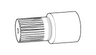
Alternator pulley remover wrench 09373-27000 |
|
Used for removing / installing alternator pulley |
Components and components location Components 1. Timing chain 2. Timing chain cam guide 3. Timing chain guide 4.
Components and components location Components ① ECM ② Battery ③ Alternator ④ Starter ⑤ Instrument Cluster ⑥ Ignition switch or start/stop button ⑦ Battery sensor ⑧ Hood switch Description and operation Description The charging system included a battery, an alternator with a built-in regulator, and the charging indicator light and wire.
Other information:
Kia Rio 2017-2023 YB Service Manual: Ignition Switch
Repair procedures Inspection 1. Disconnect the key warning switch connector (A) and ignition switch connector (B) from the steering column. 2. Check for continuity between the terminals.
Kia Rio 2017-2023 YB Service Manual: Power Windows
Components and components location Component Location 1. Driver power window switch 2. Assist power window switch 3. Rear power window switch 4. Front window motor 5. Rear window motor Description and operation Safety Function of Power Window When driver door power win
Categories
- Manuals Home
- Kia Rio Owners Manual
- Kia Rio Service Manual
- Motor Driven Power Steering
- Engine Electrical System
- Cooling System
- New on site
- Most important about car
