Kia Rio: Charging System / Alternator
Specifications
| Specification |
▷ 13.5V, 90A
|
Item |
Specification |
|
Rated voltage |
13.5V, 90A |
|
Speed in use |
1,000 - 18,000 rpm |
|
Voltage regulator |
IC Regulator built-in type |
|
Regulator Setting Voltage (Internal mode) |
14.55 ± 0.3V |
|
Connector |
3 Pin (C, FR, L) |
▷ 13.5V, 130A
|
Item |
Specification |
|
Rated voltage |
13.5V, 130A |
|
Speed in use |
1,000 - 18,000 rpm |
|
Voltage regulator |
IC Regulator built-in type |
|
Regulator Setting Voltage (Internal mode) |
14.55 ± 0.3V |
|
Connector |
3 Pin (C, FR, L) |
|
Pully Type |
OAP |
Components and components location
| Components |
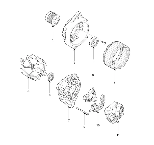
| 1. OAP
(Overrunning Alternator Pully) 2. Front Bracket 3. Front Bearing 4. Stator 5. Rotor 6. Rear Bearing |
7. Rear
Bracket 8. Brush Holder Assembly 9. Through Bolt 10. Rectifier Assembly 11. Rear Cover |
Description and operation
| Description |
The Alternator has eight built-in diodes, each rectifying AC current to DC current.
Therefore, DC current appears at alternator "B" terminal.
In addition, the charging voltage of this alternator is regulated by the battery voltage detection system.
The alternator is regulated by the battery voltage detection system.
The main components of the alternator are the rotor, stator, rectifier, capacitor brushes, bearings and V-ribbed belt pulley.
The brush holder contains a built-in electronic voltage regulator.
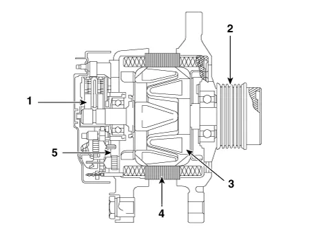
| 1. Brush 2. Over-running Alternator (OAP) Pulley 3. Rotor 4. Stator 5. Rectifier |
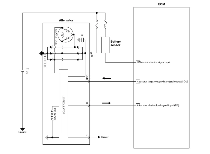
Schematic diagrams
| Circuit Diagram |
| [130A Type] |
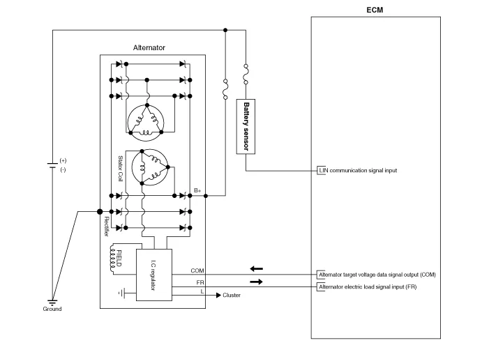
| [90A Type] |
|

Repair procedures
| Removal |
| 1. |
Disconnect the battery negative (-) terminal. |
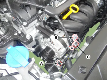
| 2. |
Disconnect the air compressor connector (A) and the alternator connector (B), and remove the cable (C) from alternator "B" terminal.
|
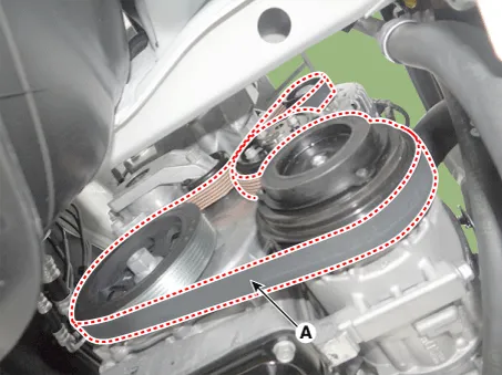
| 3. |
Remove the drive belt (A).
|
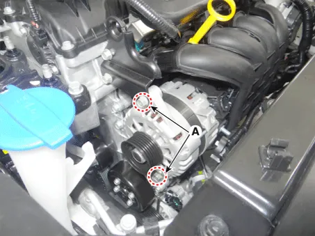
| 4. |
Remove the alternator lower bolt and upper bolt (A).
|
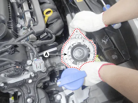
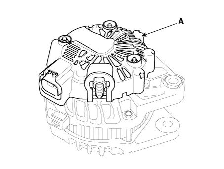
| 5. |
Remove the alternator (A).
|
| Installation |
| 1. |
Install in the reverse order of removal. |
| 2. |
Adjust the alternator belt tension after installation. (Refer to Engine Mechanical System - "Drive Belt") |
| 3. |
Install the alternator. |
| Disassembly |
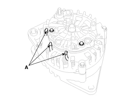
| 1. |
Remove the rear cover (A) after removing nuts.
|
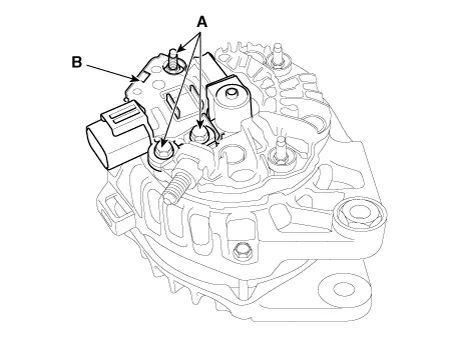
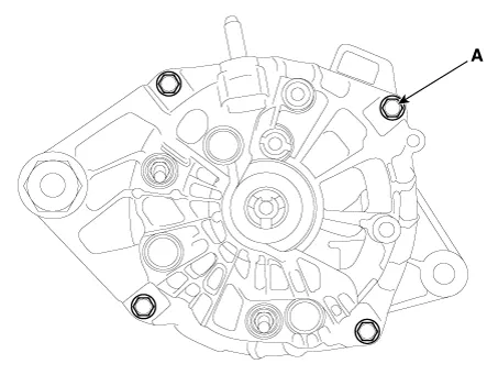
| 2. |
Remove the mounting bolts (A) and the brush holder assembly (B).
|
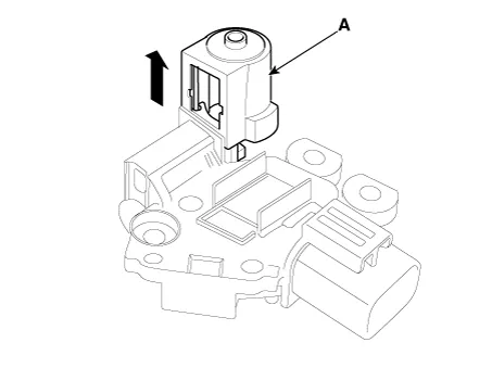
| 3. |
Remove the slip ring guide (A) after pulling it.
|
| 4. |
Remove the OAD(Overrunning Alternator Decoupler) cap.
|

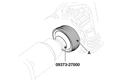
| 5. |
Remove the OAD(Overrunning Alternator Decoupler) pulley (A) using the special tool.
|
| 6. |
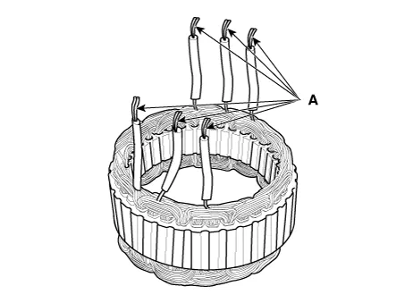
Unsolder the 3 stator leads (A).
|
| 7. |
Remove the 4 through bolts (A).
|
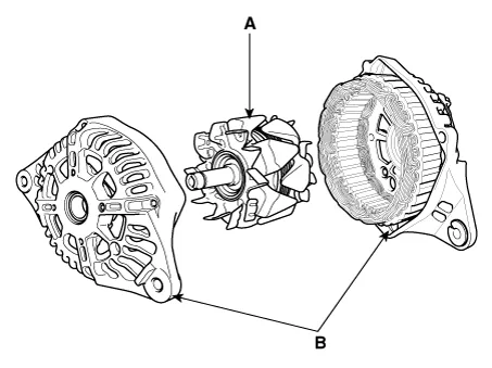
| 8. |
Disconnect the rotor (A) and bracket (B).
|
| Reassembly |
| 1. |
Reassemble in the reverse order of disassembly.
|
| Inspection |
| [Rotor] |
| 1. |
Check that there is continuity between the slip rings (A). |
| 2. |
Check that there is no continuity between the slip rings and the rotor (B) or rotor shaft (C).
|
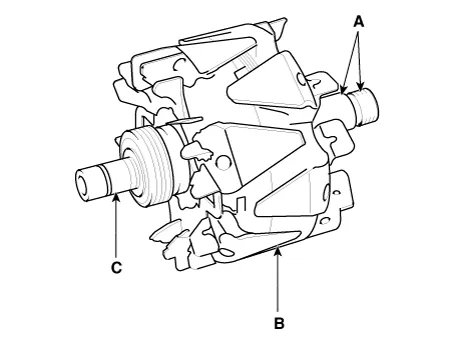
| 3. |
If the rotor fails either continuity check, replace the alternator. |
| [Stator] |
| 1. |
Check that there is continuity between each pair of leads (A).
|
| 2. |
Check that there is no continuity between each lead and the coil core. |
| 3. |
If the coil fails either continuity check, replace the alternator. |
Components and components location Components ① ECM ② Battery ③ Alternator ④ Starter ⑤ Instrument Cluster ⑥ Ignition switch or start/stop button ⑦ Battery sensor ⑧ Hood switch Description and operation Description The charging system included a battery, an alternator with a built-in regulator, and the charging indicator light and wire.
Description and operation Description Due to the considerably more frequent occurrence of starting operations, the electrical load that occurs often leads to voltage dips in the vehicle network.
Other information:
Kia Rio 2017-2023 YB Service Manual: Rear Glass Defogger Printed Heater
Repair procedures Inspection • Wrap tin foil around the end of the voltmeter test lead to prevent damaging the heater line. Apply pressure on the tin foil with hand and move the tin foil along the grid line to check for open circ
Kia Rio 2017-2023 YB Service Manual: Heating,Ventilation, Air Conditioning
Specifications Specification Air Conditioner Item Specification Compressor Type DVE12 Oil type & Capacity PAG 30, 120 ± 10 g Displacement 122 cc/rev Expansion valve Type
Categories
- Manuals Home
- Kia Rio Owners Manual
- Kia Rio Service Manual
- General Information
- Body Electrical System
- Timing Chain
- New on site
- Most important about car
