Kia Rio: Charging System / DC/DC Converter
Description and operation
| Description |
Due to the considerably more frequent occurrence of starting operations, the electrical load that occurs often leads to voltage dips in the vehicle network.
In order to stabilize the power supply for certain voltage-sensitive electrical components, a DC/DC converter is used in conjunction with the ISG function.
The DC/DC converter supplies the relay with a voltage that also remains constant during the starting operation.
The DC/DC converter is fitted at the behind of the glove box.
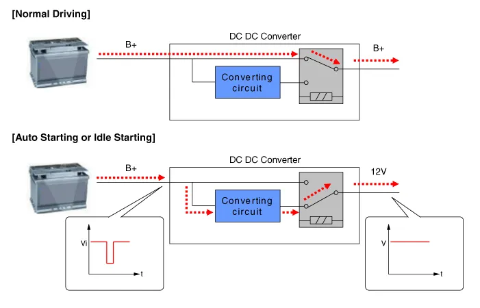
Via the test leads for input voltage and the start relay , the electronics decide whether the power is supplied to the output via the bypass or the DC/DC converter.
In the bypass mode, the on-board supply voltage is not fed across the DC/DC converter, rather is transferred directly to the outputs. In the booster phase, the vehicle voltage is adapted.
| Operation Principle |
|

Components and components location
| Component Location |

| 1. DC/DC converter (LHD) |
2. DC/DC converter (RHD) |
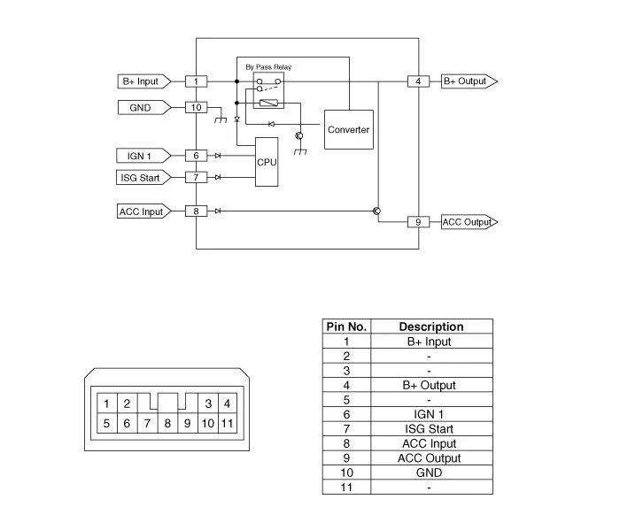
Schematic diagrams
| Circuit Diagram |
Repair procedures
| Removal |
| 1. |
Disconnect the battery negative terminal. |
| 2. |
Remove the glove box housing. (Refer to Body - "Glove Box Housing") |
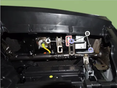
| 3. |
Disconnect the DC/DC converter conector (A). |
| 4. |
Remove the DC/DC converter (B) after removing nuts.
[LHD]
[RHD]
|

| Installation |
| 1. |
Install in the reverse order of removal.
|

Specifications Specification ▷ 13.5V, 90A Item Specification Rated voltage 13.
Specifications Specification ▷ AGM60L-DIN Item Specification Capacity [20HR/5HR] (AH) 60/48 Cold Cranking Amperage (A) 640 (SAE) / 640(EN) Reserve Capacity (Min) 100 • Model type description • Cold Cranking Ampere (CCA): Cold Cranking Amps is a rating used in the battery industry to define a battery's ability to start an engine in cold temperatures.
Other information:
Kia Rio 2017-2023 YB Service Manual: Power Door Mirror Switch
Components and components location Component Driver Power Window Switch Schematic diagrams Circuit Diagram [Non-Folding Mirror Type] [Folding Mirror Type] Repair procedures Removal 1.
Kia Rio 2017-2023 YB Service Manual: Rear Glass Defogger Switch
Repair procedures Inspection 1. In the body electrical system, failure can be quickly diagnosed by using the vehicle diagnostic system (KDS/GDS). The diagnostic system (KDS/GDS) provides the following information. (1) Self diagnosis : Checking failure and code number (DTC)
Categories
- Manuals Home
- Kia Rio Owners Manual
- Kia Rio Service Manual
- Body (Interior and Exterior)
- Maintenance
- Coolant
- New on site
- Most important about car
