Kia Rio: Cruise Control System / Cruise Control Switch
Components and components location
| Components |
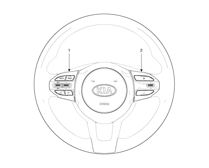
| 1. Left Remote Control Switch
(Audio + Hands free + Voice) |
2. Right Remote Control Switch
(Cruise+Trip Computer) |
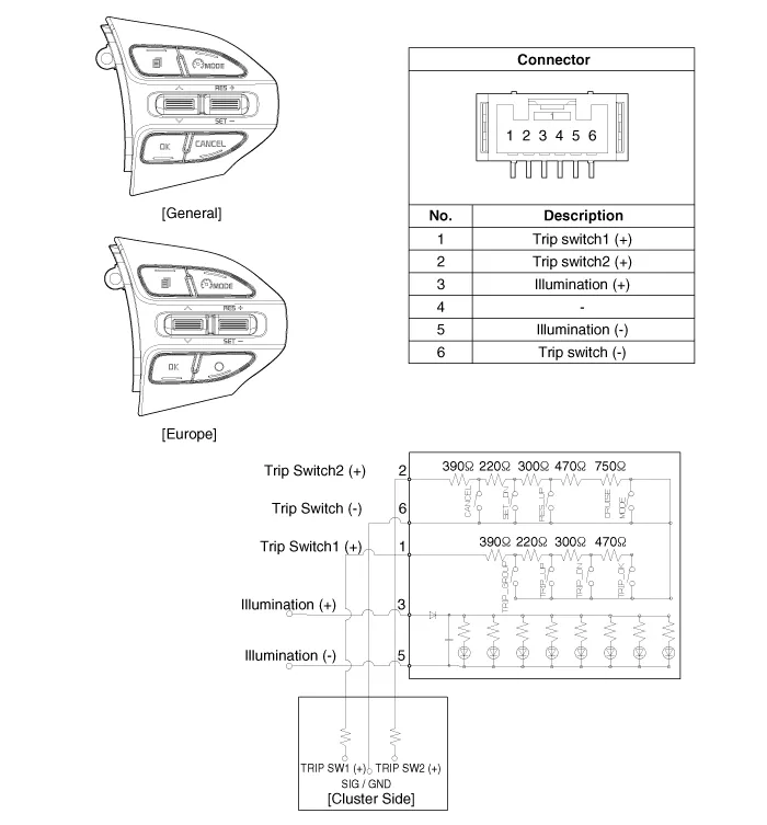
Schematic diagrams
| Circuit Diagram |
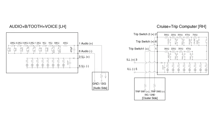
| [Audio] |

| [Audio + Bluetooth] |
| [Audio + Bluetooth + Voice] |
| [Trip] |
| [Trip + ACC (2 Button)] |
| [Trip + ACC + SLD (2 Button)] |
| [Trip + ACC (4 Button)] |
| [Trip + ACC + SLD (4 Button)] |
Repair procedures
| Removal |
| 1. |
Disconnect the negative (-) battery terminal. |
| 2. |
Remove the steering wheel assembly. (Refer to Steering System - "Steering Wheel") |
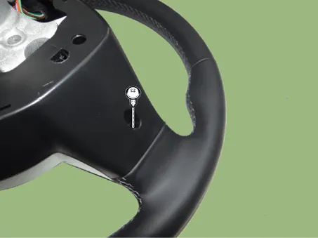
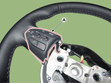
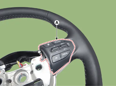
| 3. |
Remove the steering wheel remote control (A) after loosening the mounting screws. [LH]
[RH]
|
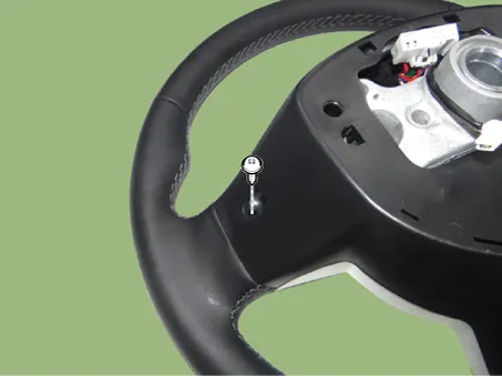
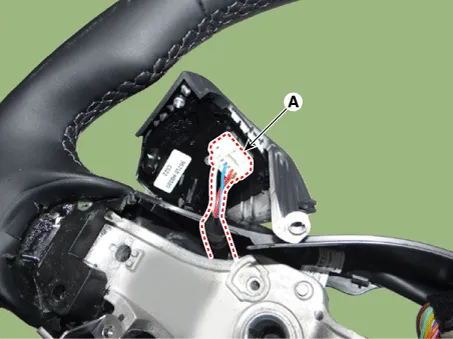
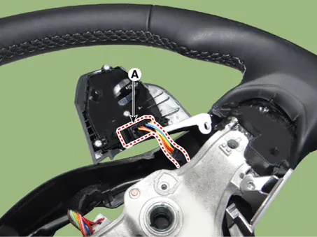
| 4. |
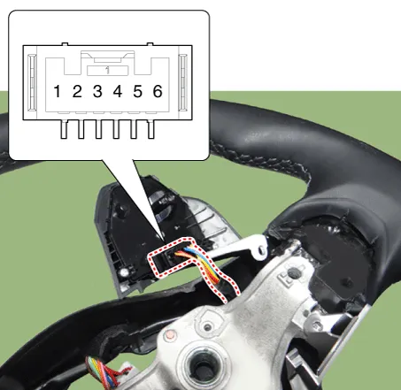
Disconnect the steering wheel remote control connector (A). [LH]
[RH]
|
| Installation |
| 1. |
Connect the steering wheel remote control connector. |
| 2. |
Install the steering wheel remote control. |
| 3. |
Install the steering wheel and driver airbag module. |
| 4. |
Connect the negative (-) battery terminal. |
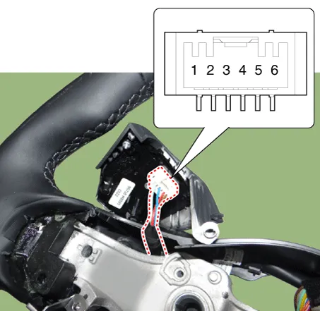
| Inspection |
| 1. |
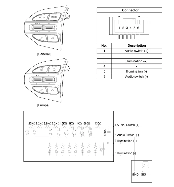
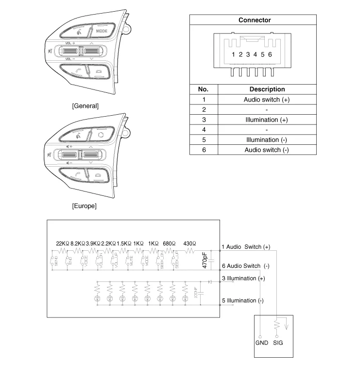
Check the resistance between terminals in each switch position (LH).
[LH : Audio + Hands free + Voice]
|
| 2. |
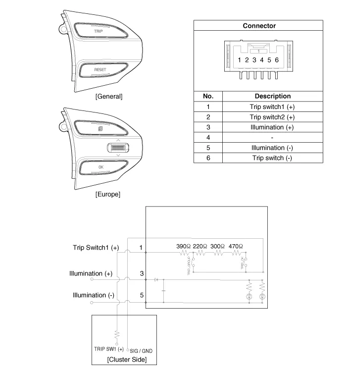
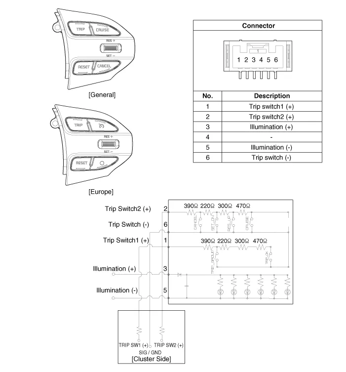
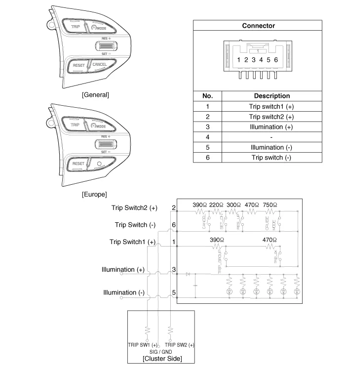
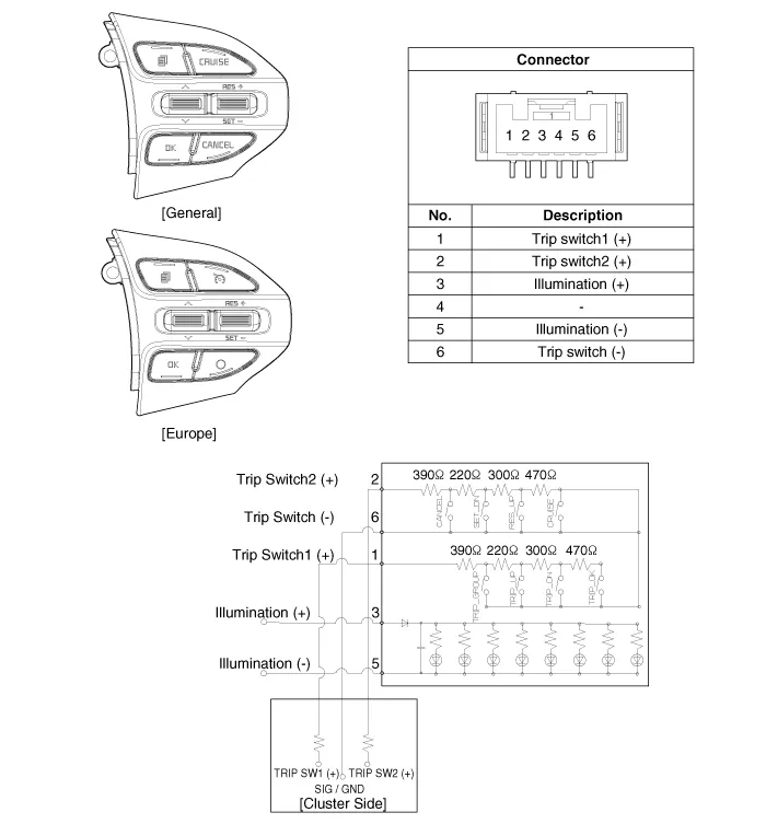
Check for resistance between terminals in each switch position (RH).
[RH : Cruise + Trip]
|
Description and operation Description The cruise control system is engaged by the cruise "ON/OFF" main switch located on right of steering wheel column.
Specifications Specifications Purge control solenoid valve (PCSV) ▷ Specification Item Specification Coil resistance (Ω) 18.
Other information:
Kia Rio 2017-2023 YB Service Manual: Power Door Mirrors
C
Kia Rio 2017-2023 YB Service Manual: Power Window Motor
Components and components location Components [Standard window motor] [Safety window motor] Repair procedures Inspection • When removing with a flat-tip screwdriver or remover, wrap protective
Categories
- Manuals Home
- Kia Rio Owners Manual
- Kia Rio Service Manual
- Engine Mechanical System
- Engine Oil and Filter
- Cooling System
- New on site
- Most important about car
