Kia Rio: Smart Key System / Smart Key Diagnostic
Repair procedures
| Inspection |
Self Diagnosis With Scan Tool
It will be able to diagnose defects of SMART KEY system with KDS/GDS quickly. KDS/GDS can operates actuator forcefully, input/output value monitoring and self diagnosis.
The following three features will be major problem in SMART KEY system.
| 1. |
Problem in SMART KEY unit input. |
| 2. |
Problem in SMART KEY unit. |
| 3. |
Problem in SMART KEY unit output. |
So the following three diagnosis operates will be the major problem solution process.
| 1. |
SMART KEY unit Input problem : switch diagnosis |
| 2. |
SMART KEY unit problem : communication diagnosis |
| 3. |
SMART KEY unit Output problem : antenna and switch output diagnosis |
Switch Diagnosis
| 1. |
Connect the cable of KDS/GDS to the data link connector in driver side crash pad lower panel, turn the power on KDS/GDS. |
| 2. |
Select the vehicle model and then SMART KEY system. |
| 3. |
Select the "SMART KEY unit". |
| 4. |
After IG ON, select the "Current data".
|
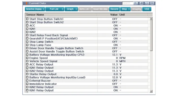
| 5. |
You can see the situation of each switch on scanner after connecting the "current data" process.
|
Communication Diagnosis With KDS/GDS (Self Diagnosis)
| 1. |
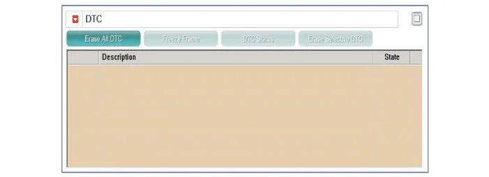
Communication diagnosis checks that the each linked components operates normal. |
| 2. |
Connect the cable of KDS/GDS to the data link connector in driver side crash pad lower panel. |
| 3. |
After IG ON, select the "DTC".
|
Antenna Actuation Diagnosis
| 1. |
Connect the cable of KDS/GDS to the data link connector in driver side crash pad lower panel. |
| 2. |
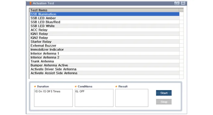
After IG ON, select the "Actation Test".
|
| 3. |
Set the smart key near the related antenna and operate it with a KDS/GDS. |
| 4. |
If the LED of smart key is blinking, the smart key is normal. |
| 5. |
If the LED of smart key is not blinking, check the voltage of smart key battery. |
| 6. |
Antenna actuation
|
Antenna Status Check
| 1. |
Connect the cable of KDS/GDS to the data link connector in driver side crash pad lower panel. |
| 2. |
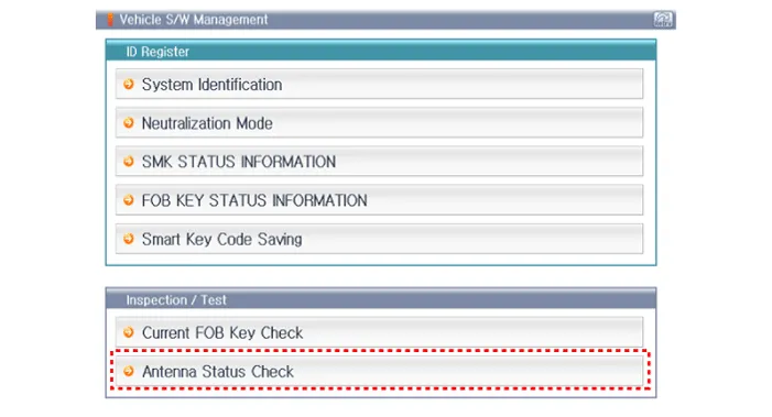
Select the "Antenna Status Check".
|
| 3. |
After IG ON, select the "Antenna Status Check".
|
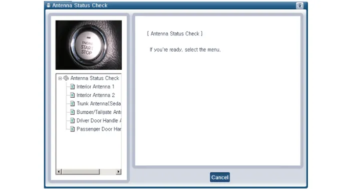
| 4. |
Set the smart key near the related antenna and operate it with a KDS/GDS.
|
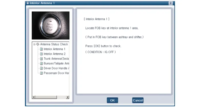

| 5. |
If the smart key runs normal , the related antenna, smart key(transmission, reception) and exterior receiver are normal. |
| 6. |
Antenna status
|
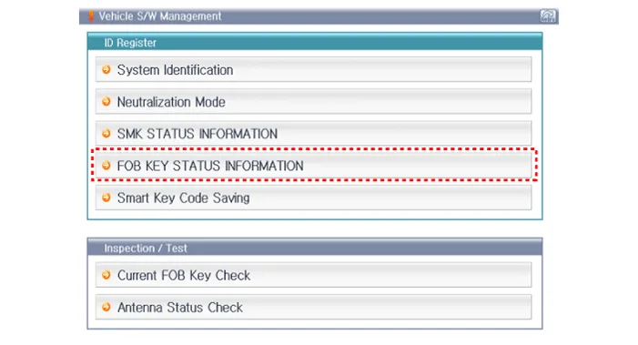
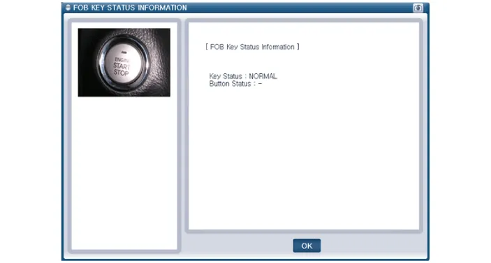
FOB Status Check
| 1. |
Connect the cable of KDS/GDS to the data link connector in driver side crash pad lower panel. |
| 2. |
After IG ON, select the "FOB KEY STATUS INFO".
|
Smart Key Status Check
| 1. |
Connect the cable of KDS/GDS to the data link connector in driver side crash pad lower panel. |
| 2. |
After IG ON, select the "SMK STATUS INFO".
|
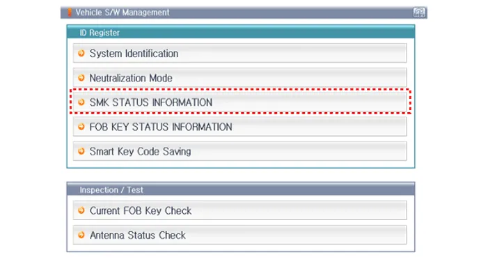

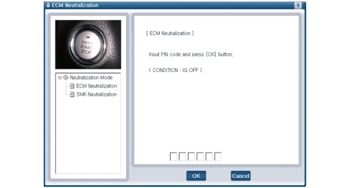
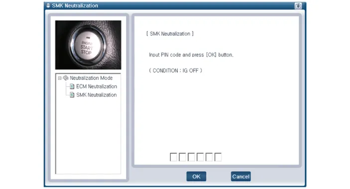
Neutralization Status Check
| 1. |
Connect the cable of KDS/GDS to the data link connector in driver side crash pad lower panel. |
| 2. |
After IG ON, select the "Neutralization mode".
|


Components and components location Components Connector Pin Information No. Connector A Connector B Connector C 1 - IGN2 Relay_output Battery (+)_Signal 2 SSB Switch1 signal_input P-CAN (Low) - 3 Driver door outside handle switch_input P-CAN (High) Immobilizer antenna (Power)_output 4 - C-CAN (High) Driver outside handle antenna (Power)_output 5 - C-CAN (Low) Passenger outside handle antenna (Power)_output 6 - SSB Amber illumination_output Bumper antenna (Power)_output 7 RPM Signal_input - Interior antenna 1 (Power)_output 8 Start signal feedback_input SSB Illumination (+)_output Interior antenna 2 (Power)_output 9 IGN2 ESCL Enable_output Interior antenna 3 (Power)_output 10 - Battery (+)_Power - 11 Starter relay_output IGN1 Relay_output - 12 Ground_Power1 ESCL (COM) - 13 SSB Switch2 signal_input EMS (COM) ESCL_Ground (-)_output 14 Assist door outside handle switch_input - Immobilizer antenna (Ground)_output 15 - SSB Illumination (-)_output Driver outside handle antenna (Ground)_output 16 AT : "P" Positon_input MT : Clutch switch_input SSB Illumination (Blue)_output SSB Illumination (Red)_output Passenger outside handle antenna (Ground)_output 17 ESCL Unlock switch_input - Bumper antenna (Ground)_output 18 Wheel speed sensor_input Exterior buzzer_output Interior antenna 1 (Ground)_output 19 ACC Signal_input - Interior antenna 2 (Ground)_output 20 IGN1 ESCL (+)_output Interior antenna 3 (Ground)_output 21 Brake switch_input - 22 ACC Relay_output Ground_Power2 Schematic diagrams Circuit Diagram Repair procedures Removal Put on gloves to prevent hand injuries.
Components and components location Component Location 1. Sunroof 2. Sunroof switch 3. Sunroof motor & controller Schematic diagrams Circuit Diagram
Other information:
Kia Rio 2017-2023 YB Service Manual: Hazard Lamp Switch
Repair procedures Inspection 1. Check for continuity between terminals. If the continuity is not as specified, replace the hazard lamp switch. No. Description No.
Kia Rio 2017-2023 YB Service Manual: Power Door Locks
Components and components location Component Location 1. Driver power window switch 2. Assist power window switch 3 . Body Comtrol Module (BCM) 4 . Tailgate actuator 5 . Door latch lock actuator 6 .
Categories
- Manuals Home
- Kia Rio Owners Manual
- Kia Rio Service Manual
- Engine Electrical System
- Coolant
- Body (Interior and Exterior)
- New on site
- Most important about car
