Kia Rio: Body Electrical System / Lighting System
Specifications
| Specification |
|
Item |
Type |
Bulb Watt (W) |
|||
|
Front |
Headlamp |
Halogen |
Low/High |
H4 LL |
55/60 |
|
Turn signal lamp |
PY21W |
21 |
|||
|
Position lamp |
W5W |
5 |
|||
|
Halogen + SBL (Position lamp) |
Low/High |
HB3 HL+ |
60 |
||
|
Turn signal lamp |
PY21W |
21 |
|||
|
Position lamp |
LED |
LED |
|||
|
Halogen + SBL (DRL / Position lamp) |
Low/High |
HB3 HL+ |
60 |
||
|
Turn signal lamp |
PY21W |
21 |
|||
|
Position lamp |
LED |
LED |
|||
|
Daytime Running Light (DRL) |
LED |
LED |
|||
|
Static bending light (SBL) |
H7 LL |
55 |
|||
|
Front fog lamp |
HB4 |
51 |
|||
|
Turn signal lamp (Side) |
WY5W |
5 |
|||
|
Door mirror turn signal lamp |
LED |
LED |
|||
|
Rear |
Rear combination lamp |
Bulb Type |
Tail lamp |
W5W L/L |
5 |
|
Tail / Stop lamp |
P21/5W L/L |
5 |
|||
|
Turn signal lamp |
PY21W L/L |
21 |
|||
|
Back up lamp |
W16W |
16 |
|||
|
LED Type |
Tail / Stop lamp |
LED |
LED |
||
|
Turn signal lamp |
PY21W |
21 |
|||
|
Back up lamp |
W16W |
16 |
|||
|
Rear fog lamp |
LED |
LED |
|||
|
High mounted stop lamp |
Bulb type |
W5W |
5 |
||
|
LED type |
LED |
LED |
|||
|
License plate lamp |
W5W |
5 |
|||
|
Interior |
Map lamp |
W10W |
10 |
||
|
Room lamp |
FESTOON |
10 |
|||
|
Luggage lamp |
FESTOON |
10 |
|||
|
Vanity lamp |
FESTOON |
5 |
|||
Components and components location
| Component Location |
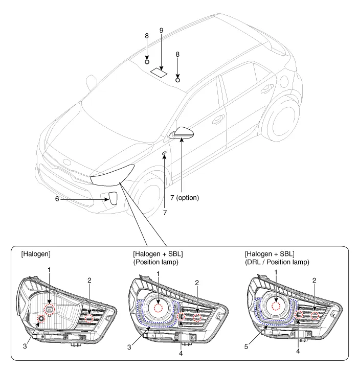
| 1 . Headlamp (Low/High Bi-function)
2. Turn signal lamp 3. Position lamp 4 . Static bending light (SBL) 5 . Daytime running light (DRL) |
6 . Fog lamp 7 . Turn signal lamp (Door mirror / Side) 8 . Vanity lamp 9 . Map lamp |
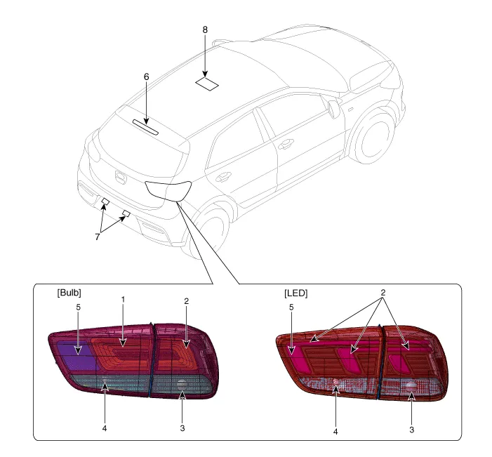
| 1 . Tail lamp 2. Stop / Tail lamp 3 . Turn signal lamp 4 . Back up lamp |
5 . fog lamp 6 . High mounted stop lamp 7 . License lamp 8. Room lamp |
- Headlamps
- Turn Signal Lamp
- Room Lamp
- Vanity Lamp
- Overhead Console Lamp
- Hazard Lamp Switch
- Rheostat
- Front Fog Lamps
- License Lamps
- High Mounted Stop Lamp
- Rear Combination Lamp
Components and components location Components Repair procedures Removal When replacing the LDWS switch, check that the symbol mark in the cluster operates normally by pressing the ON/OFF switch.
Description and operation Description BI-FUNCTION 1. Definition – A headlamp with integrated functions of high and low beam – The light is controlled by rotating the shield inserted to the lens.
Other information:
Kia Rio 2017-2023 YB Service Manual: Rear Glass Defogger Switch
Repair procedures Inspection 1. In the body electrical system, failure can be quickly diagnosed by using the vehicle diagnostic system (KDS/GDS). The diagnostic system (KDS/GDS) provides the following information. (1) Self diagnosis : Checking failure and code number (DTC)
Kia Rio 2017-2023 YB Service Manual: Condenser
Repair procedures Inspection 1. Check the condenser fins for clogging and damage. If clogged, clean them with water, and blow them with compressed air. If bent, gently bend them using a screwdriver or pliers. 2.
Categories
- Manuals Home
- Kia Rio Owners Manual
- Kia Rio Service Manual
- Brake System
- Engine Electrical System
- Emission Control System
- New on site
- Most important about car
