Kia Rio: Rear Glass Defogger / Rear Glass Defogger Switch
Repair procedures
| Inspection |
| 1. |
In the body electrical system, failure can be quickly diagnosed by using the vehicle diagnostic system (KDS/GDS). The diagnostic system (KDS/GDS) provides the following information.
|
| 2. |
Select the 'Car model' and the 'Body Control Module (BCM)' to be checked in order to check the vehicle with the tester. |
| 3. |
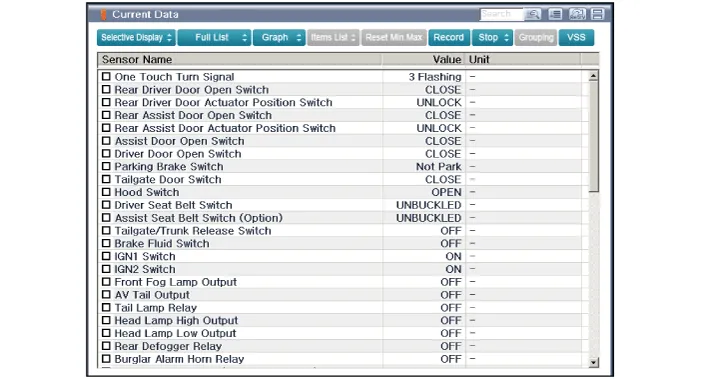
Select the 'Current Data' menu to search the current state of the input/output data.
|
| 4. |
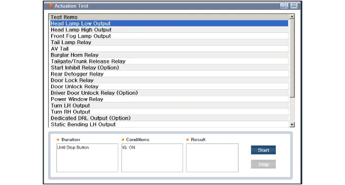
To forcibly actuate the input value of the module to be checked, select option 'Actuation Test'
|
| Removal |
| 1. |
Disconnect the negative (-) battery terminal. |
| 2. |
Remove the heater and A/C controll unit. (Refer to Heating, Ventilation, Air conditioning - "Heater & A/C Control Unit (MANUAL)") (Refer to Heating, Ventilation, Air conditioning - "Heater & A/C Control Unit (FATC)") |
| Installation |
| 1. |
Install the heater and A/C control unit. |
| 2. |
Connect the negative (-) battery terminal. |
Repair procedures Inspection • Wrap tin foil around the end of the voltmeter test lead to prevent damaging the heater line.
Components and components location Component Location 1 . Rear wiper arm & blade 2 . Rear wiper arm nut 3 . Rear wiper grommet 4 .
Other information:
Kia Rio 2017-2023 YB Service Manual: Hazard Lamp Switch
Repair procedures Inspection 1. Check for continuity between terminals. If the continuity is not as specified, replace the hazard lamp switch. No. Description No.
Kia Rio 2017-2023 YB Service Manual: Climate Control Air Filtar
Description and operation Description The climate control air filter is located in the bower unit. It eliminates foreign materials and odor. The particle filter performs a role as an odor filter as well as a conventional dust filter to ensure comfortable interior environment.
Categories
- Manuals Home
- Kia Rio Owners Manual
- Kia Rio Service Manual
- Coolant
- Maintenance
- Suspension System
- New on site
- Most important about car
