Kia Rio: Power Door Mirrors / Power Door Mirror Actuator
Components and components location
| Components |
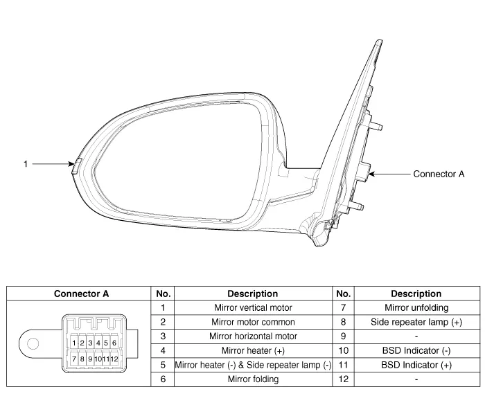
| 1. Side repeater lamp |
Repair procedures
| Inspection |
| 1. |
Disconnect the negative (-) battery terminal. |
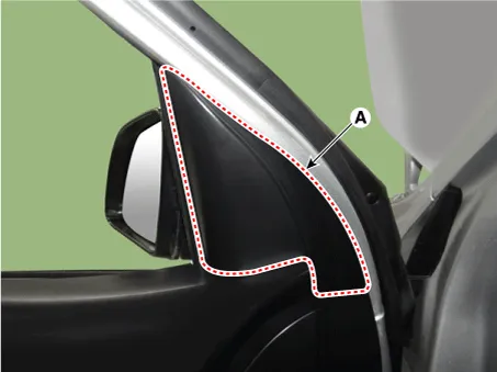
| 2. |
Remove the front door quadrant inner cover (A).
|
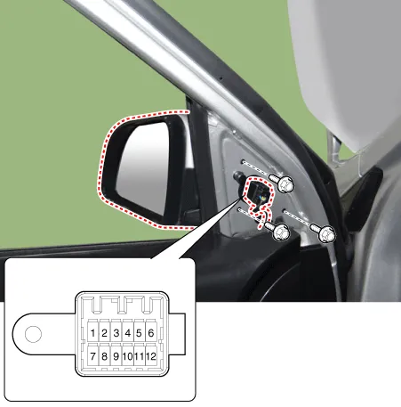
| 3. |
Disconnect the power door mirror connector from the harness.
|
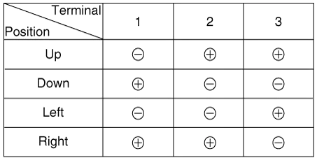
| 4. |
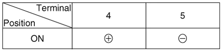
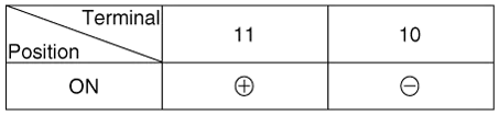
Apply battery voltage to each terminal as shown in the table and verify that the mirror operates properly. [Mirror Control (LH/RT)]
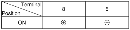
[Mirror Heater]
[Side Repeater Lamp]
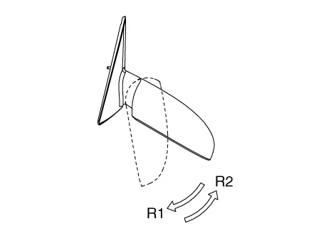
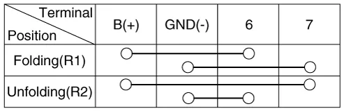
[Folding Mirror]
[BSD Indicator]
|
| Removal |
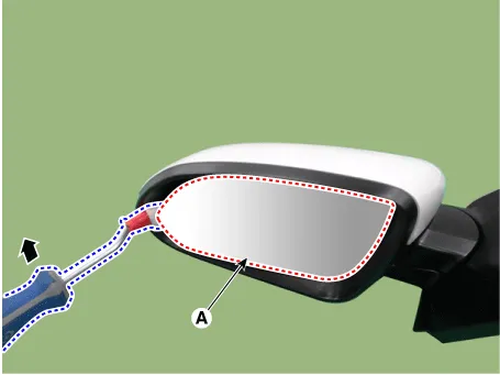
| 1. |
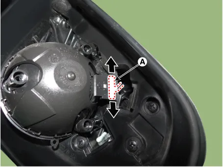
After inserting the flat-bladed screwdriver or remover as shown in the illustration below, remove the mirror (A) by applying a momentary force.
|

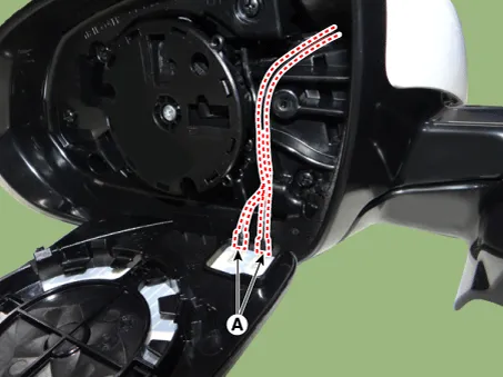
| 2. |
Disconnect the heater connectors (A).
|
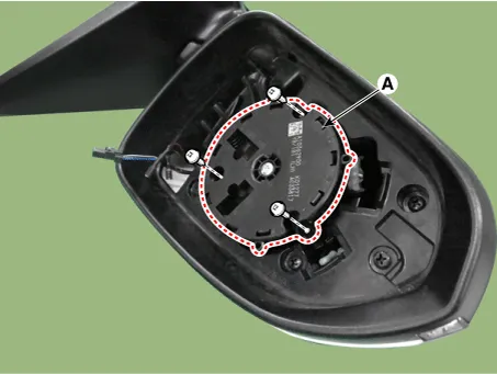
| 3. |
Remove the mirror actuator (A) after loosening the screws.
|
| 4. |
Disconnect the mirror actuator connector (A).
|
| Installation |
| 1. |
Install in the reverse order of removal. |
Components and components location Component Driver Power Window Switch Schematic diagrams Circuit Diagram [Non-Folding Mirror Type] [Folding Mirror Type] Repair procedures Removal 1.
Components and components location Component Location 1. Driver power window switch 2. Assist power window switch 3.
Other information:
Kia Rio 2017-2023 YB Service Manual: Front Washer Motor
Repair procedures Inspection Front Washer Motor 1. With the washer motor connected to the reservoir tank, fill the reservoir tank with water. • Before filling the reservoir tank wi
Kia Rio 2017-2023 YB Service Manual: Compressor Oil
Repair procedures Oil Specification 1. The HFC-134a system requires synthetic compressor oil (PAG) whereas the R-12 system requires mineral compressor oil. The two oils must never be mixed. 2. Compressor oil (PAG) varies according to compressor model.
Categories
- Manuals Home
- Kia Rio Owners Manual
- Kia Rio Service Manual
- Body Electrical System
- Engine Control / Fuel System
- Maintenance Schedule
- New on site
- Most important about car
