Kia Rio: Power Door Mirrors / Power Door Mirror Switch
Components and components location
| Component |
| Driver Power Window Switch |
Schematic diagrams
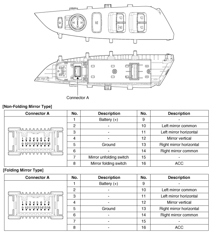
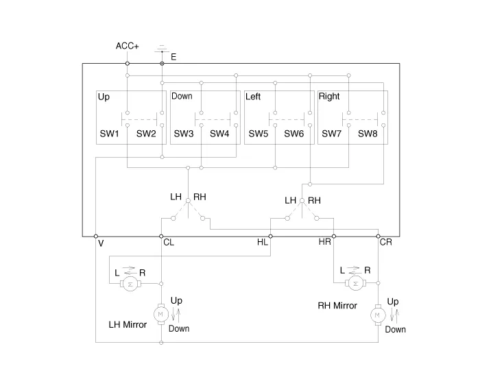
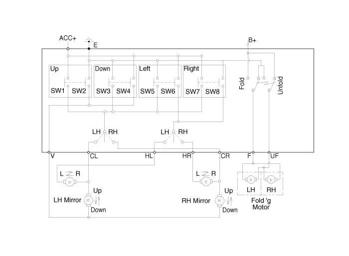
| Circuit Diagram |
| [Non-Folding Mirror Type] |
| [Folding Mirror Type] |
Repair procedures
| Removal |
| 1. |
Disconnect the negative (-) battery terminal. |
| 2. |
Remove the front left door trim. (Refer to Body - "Front Door Trim") |
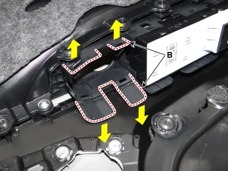
| 3. |
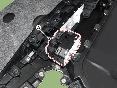
Remove the power mirror switch assembly (A) by pulling out both ends of the switch holders (B).
|
| Installation |
| 1. |
Install the power mirror switch. |
| 2. |
Install the front door trim after connecting the connector. |
| 3. |
Connect the negative (-) battery terminal. |
| Inspection |
| 1. |
Remove the front left door trim. (Refer to Body - "Front Door Trim") |
| 2. |
Remove the power mirror switch (A) from the door trim.
|
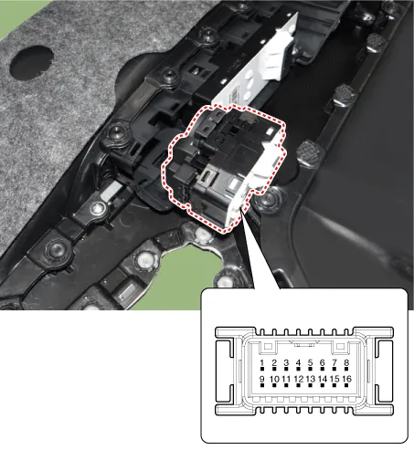
| 3. |
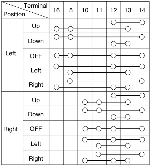
Check for continuity between the terminals in each switch position according to the table. [Power Mirror Switch]
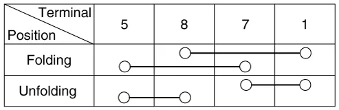
[Power Folding Mirror Switch]
|
Components and components location Component Location 1. Power door mirror 2. Power door mirror switch 3. Power folding mirror switch
Components and components location Components 1. Side repeater lamp Repair procedures Inspection 1.
Other information:
Kia Rio 2017-2023 YB Service Manual: Refrigerant line
Repair procedures Replacement 1. Discharge refrigerant from refrigeration system. 2. Replace faulty tube or hose. Cap the open fittings immediately to keep moisture or dirt out of the system.
Kia Rio 2017-2023 YB Service Manual: Compressor
Description and operation Description The compressor is the power unit of the A/C system. It is located on the side of engine block and driven by a V-belt of engine. The compressor changes the low pressure and low temperature refrigerant gas into the high pressure and high temperature refrigerant gas.
Categories
- Manuals Home
- Kia Rio Owners Manual
- Kia Rio Service Manual
- Steering System
- Cooling System
- Clutch System
- New on site
- Most important about car
