Kia Rio: Clutch System
Specifications
| Specifications |
|
Items |
Specifications |
|
|
Clutch operation method |
Hydraulic type |
|
|
Clutch cover |
Type
|
Diaphragm spring strap |
|
Clutch disc Type |
Type
|
Single dry with diaphragm |
|
Facing diameter (Outer × inner) |
Gasoline 1.4 : Ø200 ± 1 × Ø130 + 0.8 mm ( Ø7.8740±0.0394 × Ø5.1181+0.0315 in.) Gasoline 1.0 T-GDI : Ø225 ± 1 × Ø155 + 0.8 mm ( Ø8.8583±0.0394 × Ø6.1024+0.0315 in.) Gasoline 1.25 : Ø225 ± 1 × Ø130 + 0.8 mm ( Ø7.4803±0.0394 × Ø5.1181+0.0315 in.) Diesel 1.4 : Ø235 ± 1 × Ø155 + 0.8 mm ( Ø9.2520±0.0394 × Ø6.1024+0.0315 in.) |
|
|
Clutch disc thickness [When free] |
Gasoline 1.0 T-GDI / 1.4 : Ø8.1 ± 0.3 mm (0.3189 ± 0.0118 in.) Diesel 1.4 : Ø8.3 ± 0.3 mm (0.3268 ± 0.0118 in.) Gasoline 1.25 : Ø7.9 ± 0.3 mm (0.3110 ± 0.0118 in.) |
|
|
Clutch disc rivet depth |
1.1 mm (0.0433 in.) |
|
| Service Standard |
|
Item |
Specification |
|
Clutch disc rivet depth |
0.3 mm (0.0118 in.) |
| Tightening Torques |
|
Item |
N·m |
kgf·m |
lb·ft |
|
Clutch pedal mounting nut |
16.7 - 25.5 |
1.7 - 2.6 |
12.3 - 18.8 |
|
Ignition lock & clutch switch mounting bolt |
2.0 - 3.9 |
0.2 - 0.4 |
1.4 - 2.9 |
|
Clutch release cylinder bleed plug |
6.8 - 9.8 |
0.7 - 1.0 |
5.0 - 7.2 |
|
Clutch cover mounting bolt (Gasoline 1.0 T-GDI, 1.25, 1.4) |
14.7 - 21.6 |
1.5 - 2.2 |
10.8 - 15.9 |
|
Clutch cover mounting bolt (Diesel 1.4) |
11.8 ~ 14.7 |
1.2 ~ 1.5 |
8.7 - 10.8 |
|
Clutch release cylinder mounting bolt |
14.7 - 21.6 |
1.5 - 2.2 |
10.8 - 15.9 |
| Lubricants |
|
Items |
Specified
lubricants |
Quantity
|
|
Clutch release cylinder assembly |
Brake fluid DOT 3 or DOT 4 |
As
required |
|
Clutch pedal shaft and bushings |
Chassis grease SAE J310a, NLGI No.1 |
|
|
Input shaft spline |
CASMOLY L9508 |
0.2 g |
|
Release bearing & Fork |
0.3 - 0.5 g |
|
|
Release Fork & Fulcrum |
0.5 - 1.0 g |
|
|
Release Cylinder & Fork |
0.4 - 0.8 g |
|
|
Clutch Release Bearing & Clutch Housing |
0.5 - 1.0 g |
Special service tools
| Special Service Tools |
|
Tool Name / Number |
Illustration |
Description |
|
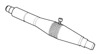
Clutch disc guide 09411-1P000 |
|
Installation of the clutch disc. |
Troubleshooting
| Troubleshooting |
|
Symptom |
Suspected Area |
Remedy |
|
Clutch grabs/chatters |
Engine mounting (Loose) |
Tighten the engine mounting. |
|
Clutch disc assembly (Excessive runout) |
Inspect the clutch disc. |
|
|
Clutch disc assembly (Oily) |
Inspect the clutch disc. |
|
|
Clutch disc assembly (Worn out) |
Replace the clutch disc. |
|
|
Clutch disc torsion spring (Damaged) |
Replace the clutch disc. |
|
|
Clutch disc assembly (Glazed) |
Inspect the clutch disc. |
|
|
Diaphragm spring (Out of alignment) |
Replace the clutch disc. |
|
|
Clutch pedal spongy |
Clutch line (Air in line) |
Perform the air bleeding. |
|
Master cylinder (Damaged) |
Replace the master cylinder. |
|
|
Release cylinder (Damaged) |
Replace the release cylinder. |
|
|
Clutch noisy |
Clutch release bearing assembly (Worn, dirty or damaged) |
Repair or replace to release bearing. |
|
Clutch slips |
Clutch disc assembly (Oily) |
Inspect the clutch disc. |
|
Clutch disc assembly (Worn out) |
Replace the clutch disc. |
|
|
Diaphragm spring (Damaged) |
Replace the clutch disc. |
|
|
Pressure plate (Distorted) |
Replace the clutch disc. |
|
|
Flywheel (Distorted) |
Replace the flywheel. |
|
|
Clutch does not disengage |
Clutch line (Air in line) |
Perform the air bleeding. |
|
Master cylinder (Damaged) |
Replace the master cylinder. |
|
|
Release cylinder (Damaged) |
Replace the release cylinder. |
|
|
Clutch disc assembly (Out of line) |
Replace the clutch disc. |
|
|
Clutch disc assembly (Excessive runout) |
Replace the clutch disc. |
|
|
Clutch disc assembly (Lining broken) |
Replace the clutch disc. |
|
|
Clutch disc assembly (Dirty or burned) |
Repair or replace to release bearing. |
|
|
Clutch disc assembly (Oily) |
Inspect the clutch disc. |
|
|
Clutch disc assembly (Lack of spline grease) |
Apply the grease to spline. |
- Clutch Cover And Disc
- Ignition Lock Switch
- Clutch Switch
- Clutch Pedal
- Clutch Master Cylinder
- Regulator
- Clutch Tube
- Clutch Release Cylinder
- Clutch Release Fork and Clutch Release Bearing
Repair procedures Removal 1. Release the residual pressure in fuel line. (Refer to Fuel Delivery System - "Release Residual Pressure in Fuel Line") When removing the fuel pump relay, a Diagnostic Trouble Code (DTC) may occur.
Components and components location Components 1. Clutch release fork 2. Clutch cover assembly 3. Clutch disk assembly 4.
Other information:
Kia Rio 2017-2023 YB Service Manual: Seat Heater
Components and components location Component Location 1. Seat heater unit (Passenger seat only) 2. Front seat back heater 3. Front seat cushion heater Schematic diagrams Circuit Diagram Repair procedures Inspection 1.
Kia Rio 2017-2023 YB Service Manual: Blower Resistor (MANUAL)
Repair procedures Inspection 1. Measure the resistance between the terminals. 2. The measured resistance is not within specification, the blower resistor must be replaced. (After removing the resistor) Replacement 1.
Categories
- Manuals Home
- Kia Rio Owners Manual
- Kia Rio Service Manual
- Cooling System
- Engine Electrical System
- Suspension System
- New on site
- Most important about car
