
Kia Rio: Seat Electrical / Seat Heater
Components and components location
| Component Location |

| 1. Seat heater unit (Passenger
seat only) 2. Front seat back heater |
3. Front seat cushion heater
|
Schematic diagrams
| Circuit Diagram |
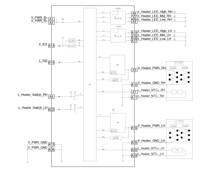
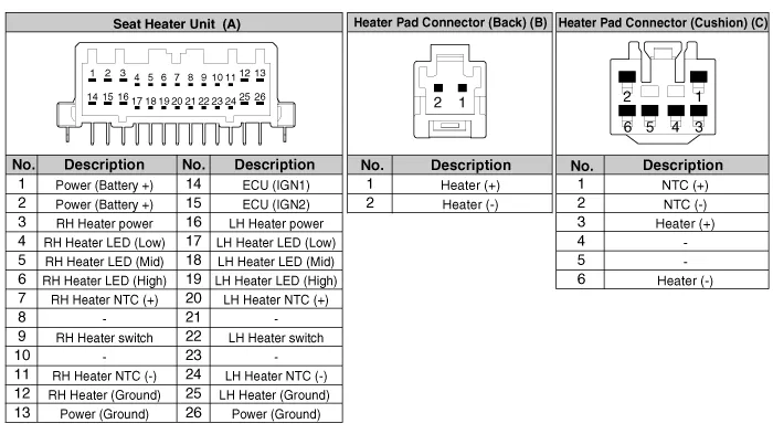
Repair procedures
| Inspection |
| 1. |
Check for continuity and measure the resistance between terminals No 3 and No 6.
|

| 2. |
Operate the seat heater after connecting the connector, and then check the thermostat by measuring the temperature of seat surface.
|
| Removal |
| 1. |
Disconnect the negative (-) battery terminal. |
| 2. |
Remove the front seat assembly. (Refer to Body - "Front Seat Assembly") |
| 3. |
Disconnect the seat heater unit connector (A).
|
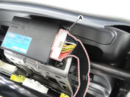
| 4. |
Remove the seat heater unit (A) after loosening the mounting screws.
|
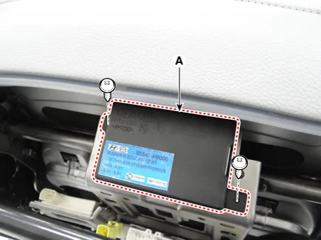
| Installation |
| 1. |
Install the seat heater unit and connecting the connector. |
| 2. |
Install the front seat assembly. |
| 3. |
Connect the negative (-) battery terminal. |
Components and components location Components 1. Driver side seat heater switch 2. Passenger side seat heater switch Description and operation Description Seat Heater Smart Control Technology • To prevent low temperature burn, seat heater temperature will automatically be lowered after a certain period of time.
Other information:
Kia Rio 2017-2023 YB Service Manual: Power Door Locks
Components and components location Component Location 1. Driver power window switch 2. Assist power window switch 3 . Body Comtrol Module (BCM) 4 . Tailgate actuator 5 . Door latch lock actuator 6 .
Kia Rio 2017-2023 YB Service Manual: Compressor Oil
Repair procedures Oil Specification 1. The HFC-134a system requires synthetic compressor oil (PAG) whereas the R-12 system requires mineral compressor oil. The two oils must never be mixed. 2. Compressor oil (PAG) varies according to compressor model.
Categories
- Manuals Home
- Kia Rio Owners Manual
- Kia Rio Service Manual
- Engine Control / Fuel System
- Fuse/relay panel description
- Timing Chain
- New on site
- Most important about car
