Kia Rio: Immobilizer System / Immobilizer Control Unit
Repair procedures
| Removal |
| 1. |
Disconnect the negative (-) battery terminal. |
| 2. |
Remove the main crash pad assembly. (Refer to Body - "Main Crash Pad Assembly") |
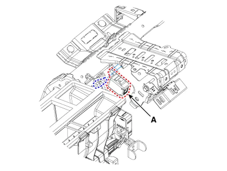
| 3. |
Disconnect the connector of the immobilizer unit and then remove the immobilizer unit (A) after loosening a bolt.
|
| Installation |
| 1. |
Install the immobilizer control unit after connecting the unit connector. |
| 2. |
Install the main crash pad assembly. |
| 3. |
Connect the negative (-) battery terminal. |
Schematic diagrams Circuit Diaram Description and operation Description The immobilizer system will disable the vehicle unless the proper ignition key is used, in addition to the currently available anti-theft systems such as car alarms, the immobilizer system aims to drastically reduce the rate of auto theft.
Repair procedures Removal 1. Disconnect the negative (-) battery terminal. 2. Remove the crash pad lower panel.
Other information:
Kia Rio 2017-2023 YB Service Manual: Front Fog Lamps
Repair procedures Removal 1. Disconnect the negative (-) battery terminal. 2. Remove the front bumper assembly. (Refer to Body - "Front Bumper Assembly") 3. Remove the front fog lamp assembly (A) after loosening the mounting screws.
Kia Rio 2017-2023 YB Service Manual: Refrigerant line
Repair procedures Replacement 1. Discharge refrigerant from refrigeration system. 2. Replace faulty tube or hose. Cap the open fittings immediately to keep moisture or dirt out of the system.
Categories
- Manuals Home
- Kia Rio Owners Manual
- Kia Rio Service Manual
- Timing Chain
- Engine Mechanical System
- Engine Control / Fuel System
- New on site
- Most important about car
