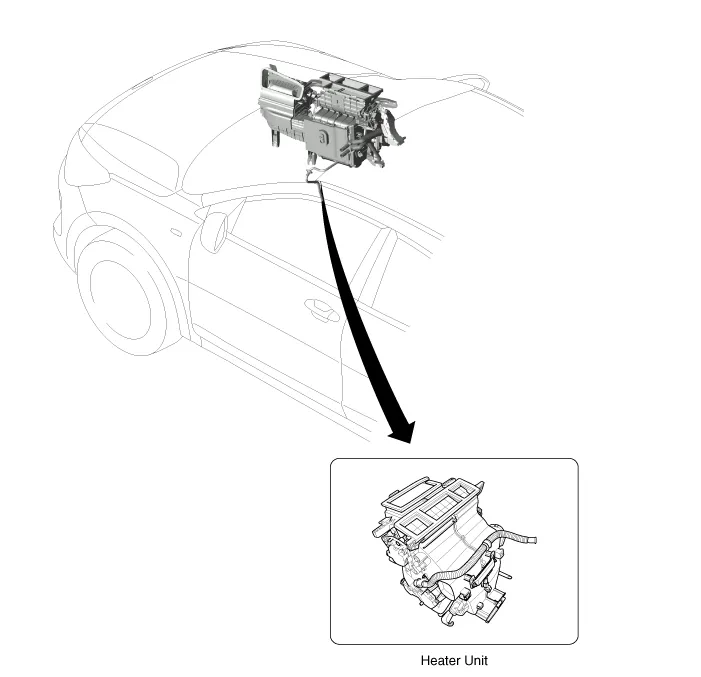
Kia Rio: Heater / Heater Unit
Components and components location
| Component Location |
| Components |
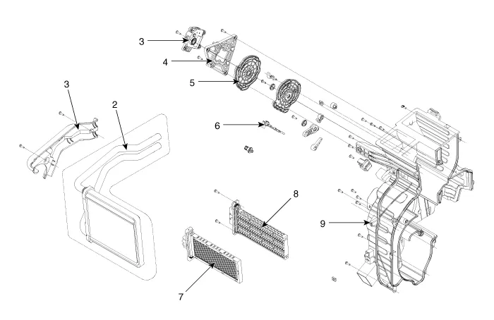
| 1. Heater pipe cover 2. Heater core 3. Mode control actuator 4. Mode control actuator bracket 5. Mode control main lever |
6. Evapoerator sensor 7. PTC Heater core(350W) 8. PTC Heater core(1000W) 9. Heater case |
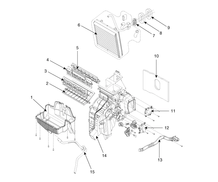
| 1. Heater lower case 2. Door assembly (TEMP) 3. Door assembly (FOOT) 4. Door assembly (VENT) 5. Door assembly (DEF) 6. Evapoerator core 7. Evapoerator Flange 8. Seal |
9. Seal (Non A/C) 10. NVH Pad 11. Defog actuator 12. Tempature control actuator 13. Aspirator hose 14. Heater case (RH) 15. Drain hose |
Repair procedures
| Replacement |
| 1. |
Disconnect the negative (-) battery terminal. |
| 2. |
Recover the refrigerant with a recovery/recycling/charging station. |
| 3. |
Drain the coolant. D 1.4 TCI-U2 (Refer to Engine Mechanical System - "Coolant") G 1.0 T-GDI-KAPPA (Refer to Engine Mechanical System - "Coolant") G 1.2 MPI-KAPPA(Refer to Engine Mechanical System - "Coolant") G 1.4 MPI-KAPPA(Refer to Engine Mechanical System - "Coolant") |
| 4. |
Remove the expansion valve (A) from the evaporator core.
|


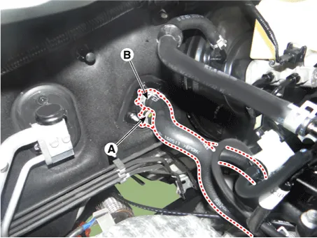
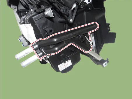
| 5. |
Disconnect the inlet (A) and outlet (B) heater hoses from the heater unit.
|

| 6. |
Remove the console assembly. (Refer to Body - "Floor Console Assembly") |
| 7. |
Remove the shift lever assembly. (Refer to Manual Transaxle System - "Shift Lever Assembly.") |
| 8. |
Lower the steering column after loosening the mounting bolts and nuts. (Refer to Steering System - "Steering Column and Shaft") |
| 9. |
Remove the wiper motor. (Refer to Body Electrical System - "Front wiper motor") |
| 10. |
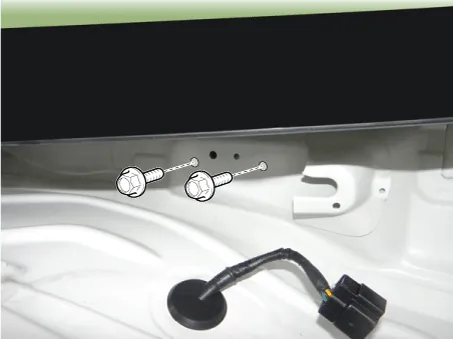
Loosen the cowl cross member mounting bolts.
|
| 11. |
Remove the crash pad. (Refer to Body - "Main Crash Pad Assembly") |
| 12. |
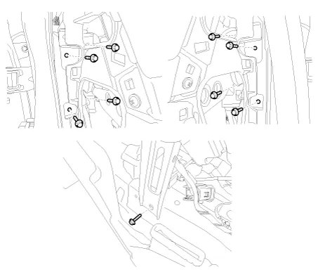
Loosen the cowl cross member mounting bolts and than remove the crash pad and heater & blower unit assembly.
|
| 13. |
Loosen the drain hose fixing clip under the vehicle. |
| 14. |
Disconnect the heater unit connectors. |
| 15. |
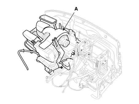
Remove the heater & blower unit (A) from the crash pad after loosening the mounting nuts.
|
| 16. |
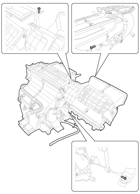
Separate the blower unit from the heater unit after loosening the screws.
|
| 17. |
Remove the heater core cover (A) after loosening the mounting screws.
|
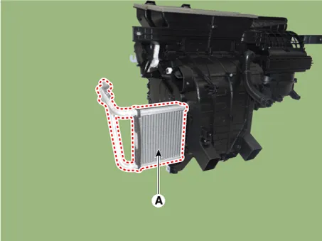
| 18. |
Pull out the heater core (A) from heater unit.
|
| 19. |
Remove the heater unit lower case (A) after loosening the mount screws.
|

| 20. |
Pull out the evaporator core (A) from heater unit.
|

| 21. |
Installation is the reverse order of removal.
|
Description and operation Description The heater unit includes mode control actuator and temperature control actuator. The temperature control actuator is located at the heater unit.
Other information:
Kia Rio 2017-2023 YB Service Manual: Vanity Lamp
Repair procedures Removal 1. Disconnect the negative (-) battery terminal. 2. Detach the vanity lamp (A) using a flat-tip screwdriver. 3. Disconnect the vanity lamp connector (A).
Kia Rio 2017-2023 YB Service Manual: Rain Sensor
Components and components location Components Schematic diagrams Circuit Diagram Description and operation Description Integrated Rain Sensor Integrated rain sensor (A) controls three systems: front wiper, auto-light, and central air conditioner.
Categories
- Manuals Home
- Kia Rio Owners Manual
- Kia Rio Service Manual
- Heating,Ventilation, Air Conditioning
- Motor Driven Power Steering
- Timing Chain
- New on site
- Most important about car
