Kia Rio: Seat Electrical / Seat Heater Switch
Components and components location
| Components |
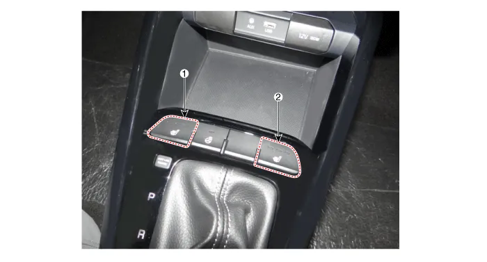
| 1. Driver side seat heater switch
|
2. Passenger side seat heater
switch |
Description and operation
| Description |
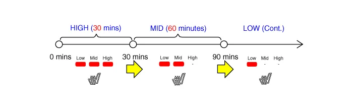
Seat Heater Smart Control Technology
| • |
To prevent low temperature burn, seat heater temperature will automatically be lowered after a certain period of time. (Low temperature burn condition: Over 30 minutes at 50°C) |
Seat Heater Smart Control Operation
| • |
Change to "MID" after 30 minutes in "HIGH", then "LOW" after 60 minutes in "MID" |
| • |
Change to "LOW" after 60 minutes in "MID" |
|

Schematic diagrams
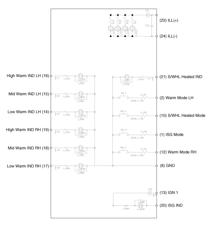
| Circuit Diagram |
Repair procedures
| Removal |
| 1. |
Disconnect the negative (-) battery terminal. |
| 2. |
Remove the front console upper cover. (Refer to Body - "Floor Console Assembly") |
| 3. |
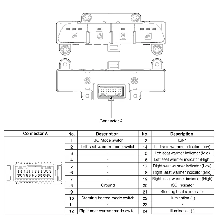
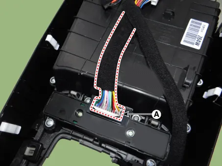
Disconnect the front console upper cover switch connector (A).
|
| 4. |
Remove the front console upper cover switch (A) after loosening the mounting screws.
|

| Installation |
| 1. |
Install the front console upper cover switch. |
| 2. |
Connect the front console upper cover switch connector. |
| 3. |
Install the front console upper cover. |
| 4. |
Connect the negative (-) battery terminal. |
Components and components location Component Location 1. Seat heater unit (Passenger seat only) 2. Front seat back heater 3.
Specifications Specifications Smart Key Unit Items Specification Rated voltage DC 12 V Operating voltage DC 9 - 16 V Operating temperature -31 - 167°F (-35 - 75°C) Load Max.
Other information:
Kia Rio 2017-2023 YB Service Manual: Power Door Lock Switch
Repair procedures Removal • When removing with a flat-tip screwdriver or remover, wrap protective tape around the tools to prevent damage to components.
Kia Rio 2017-2023 YB Service Manual: Rain Sensor
Components and components location Components Schematic diagrams Circuit Diagram Description and operation Description Integrated Rain Sensor Integrated rain sensor (A) controls three systems: front wiper, auto-light, and central air conditioner.
Categories
- Manuals Home
- Kia Rio Owners Manual
- Kia Rio Service Manual
- Emission Control System
- Coolant
- Maintenance
- New on site
- Most important about car
