Kia Rio: Clutch System / Clutch Release Cylinder
Components and components location
| Components |
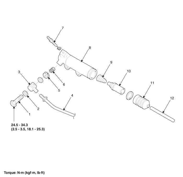
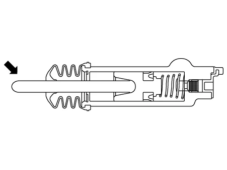
| 1. Union bolt 2. Gasket 3. Tube joint 4. Clutch tube 5. Valve plate 6. Valve spring |
7. Bleeder screw 8. Release cylinder 9. Return spring 10. Piston 11. Boot 12. Push rod |
Repair procedures
| Removal |
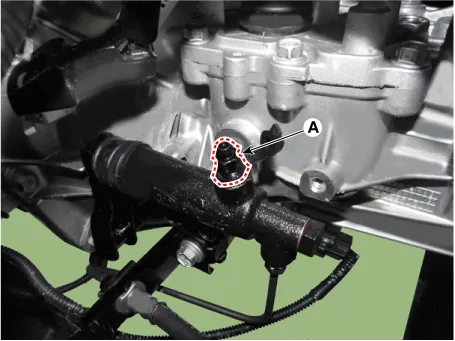
[Gasoline 1.2]
| 1. |
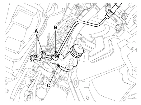
Drain the brake fluid through the bleed plug (A).
|

| 2. |
Loosen the release cylinder bolts (A) and then clutch tube nut (B) after removing release cylinder assembly (C ).
|
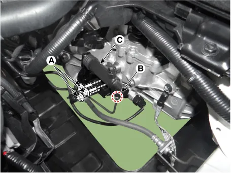
[Gasoline 1.0 T-GDI, 1.4, Diesel 1.4]
| 1. |
Drain the brake fluid through the bleed plug (A).
|
| 2. |
Loosen the release cylinder bolts (A) and then clutch tube nut (B) after removing release cylinder assembly ©.
|
| Installation |
| 1. |
Install in the reverse order of removal.
|
| Inspection |
| 1. |
Check the clutch release cylinder for fluid leakage. |
| 2. |
Check the clutch release cylinder boot for damage. |
| Adjustment |
Clutch Release Cylinder Air Bleeding Procedure
Use the specified fluid. Avoid mixing different brands of fluid. |
| 1. |
After disconnecting a cap from the clutch release cylinder air bleeder, insert a vinyl hose in the plug. |
| 2. |
Refill the clutch master cylinder with the specified fluid.
|
| 3. |
Loosening the plug screw, press and release the clutch pedal about 10 times. |
| 4. |
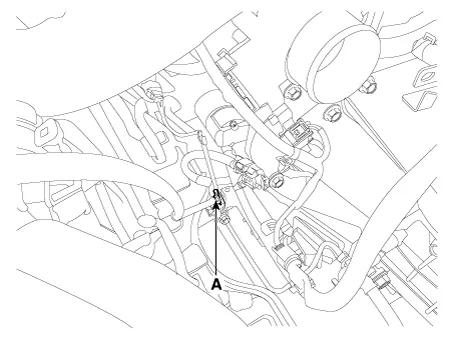
Tighten the plug (A) during the clutch pedal pressed. Afterwards, raise the pedal with a hand. |
| 5. |
After pressing the clutch pedal 3 times more, loosen the plug (A) and re-tighten it with the pedal pressed. Raise it again, then.
|
| 6. |
Repeat the step 4 two or three times. (until there is no bubble in the fluid) [Gasoline 1.2]
[Gasoline 1.0 T-GDI, 1.4, Diesel 1.4]
|
| 7. |
Refill the clutch master cylinder with the specified fluid. |
Components and components location Components [Gasoline 1.2, 1.4] 1. Clutch pedal assembly 2. Ignition lock and clutch switch 3.
Components and components location Components 1. Clutch release fork 2. Clutch cover assembly 3. Clutch disk assembly 4.
Other information:
Kia Rio 2017-2023 YB Service Manual: Rear Parking Assist System
Specifications Specification Item Specification Ultrasonic sensor Voltage rating DC 12V Detecting range 11.8 - 47.2 in (30 - 120 cm) Operation voltage DC 9 - 16 V Operation current
Kia Rio 2017-2023 YB Service Manual: Heater Unit
Components and components location Component Location Components 1. Heater pipe cover 2. Heater core 3. Mode control actuator 4. Mode control actuator bracket 5. Mode control main lever 6.
Categories
- Manuals Home
- Kia Rio Owners Manual
- Kia Rio Service Manual
- Steering System
- Body (Interior and Exterior)
- General Information
- New on site
- Most important about car
