Kia Rio: Clutch System / Clutch Release Fork and Clutch Release Bearing
Components and components location
| Components |
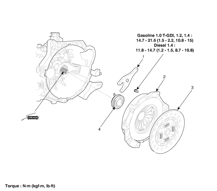
| 1. Clutch release fork 2. Clutch cover assembly |
3. Clutch disk assembly 4. Clutch release bearing |
[Gasoline 1.2 only]

| 1. Clutch disc 2. Clutch cover 3. Clutch release bearing |
4. Clutch release lever assembly
5. Cltuch release fork 6. Return clip |
Repair procedures
| Removal |
[Gasoline 1.2]
| 1. |
Remove the transaxle assembly. G 1.2 MPI (Refer to Manual Transaxle System - "Manual Transaxle") |
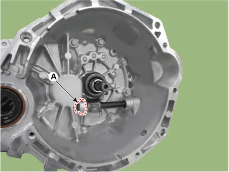
| 2. |
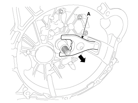
Remove the reamer bolt (A).
|

| 3. |
Remove the return clip (A).
|

| 4. |
Remove the clutch release fork.
|
[Gasoline 1.0 T-GDI, 1.4, Diesel 1.4]
| 1. |
Remove the transaxle assembly. D 1.4 U2 TCI (Refer to Manual Transaxle System - "Manual Transaxle") G 1.0 T-GDI (Refer to Manual Transaxle System - "Manual Transaxle") G 1.4 MPI (Refer to Manual Transaxle System - "Manual Transaxle") |
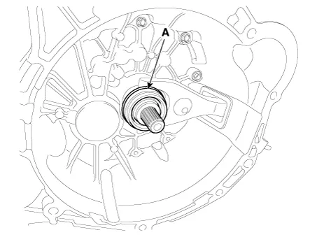
| 2. |
Remove the clutch release bearing (A).
|
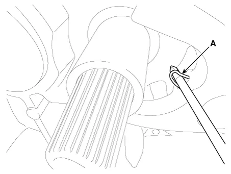
| 3. |
Pull the clip (A).
|
| 4. |
Remove the clutch release fork (A).
|
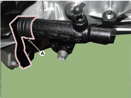
| 5. |
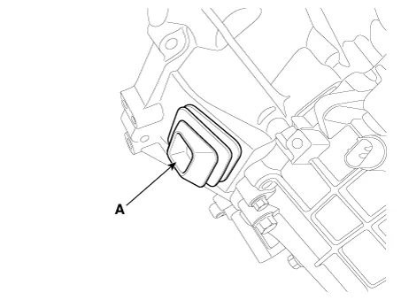
Remove the boot (A).
|
| Inspection |
| 1. |
Check for damage to boot. |
| 2. |
Check for deformation to clutch release fork. |
| 3. |
Check for deformation to clutch release bearing. |
| Installation |
| 1. |
Install the boot (A).
|
| 2. |
Install the clip to the clutch release fork. |
| 3. |
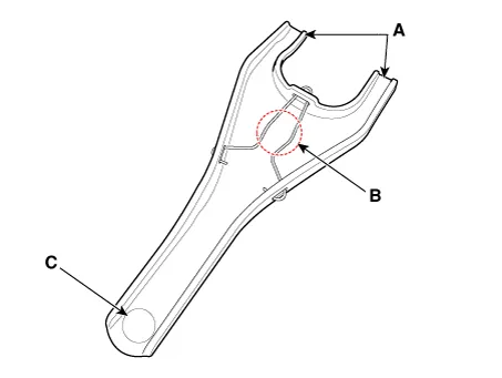
Apply to grease in location A, B and C.
|
| 4. |
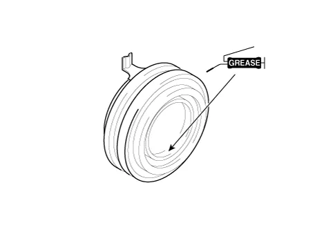
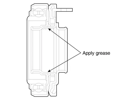
Apply the grease to the hole surface of the clutch release bearing all around.
|
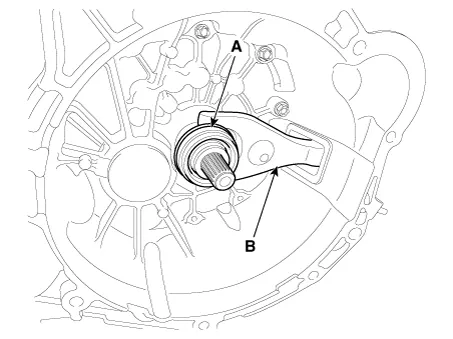
| 5. |
Install the clutch release fork (B), clutch release bearing (A).
|
| 6. |
Install the transaxle assembly. D 1.4 U2 TCI (Refer to Manual Transaxle System - "Manual Transaxle") G 1.0 T-GDI (Refer to Manual Transaxle System - "Manual Transaxle") G 1.4 MPI (Refer to Manual Transaxle System - "Manual Transaxle") |
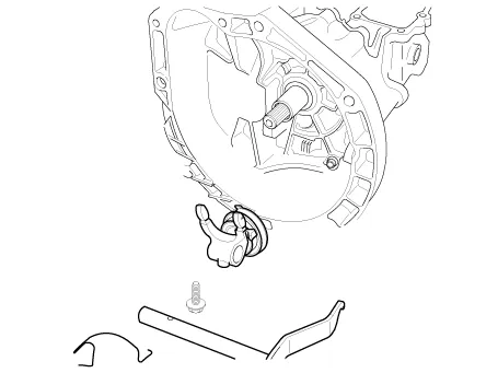
[Gasoline 1.2]
| 1. |
Apply multi purpose grease to release fork assembly.
|

| 2. |
Apply multi purpose grease into the groove of the release bearing.
|
| 3. |
Install the release bearing and release fork to clutch housing.
|
| 4. |
Install the reamer bolt (A).
|
| 5. |
Apply multi purpose grease to on contact surface of release cylinder and lever (A).
|

| 6. |
Clean the surfaces of the flywheel and pressure plate throughly with fine sandpaper or crocus cloth, and make certain that all oil or grease has been removed. |
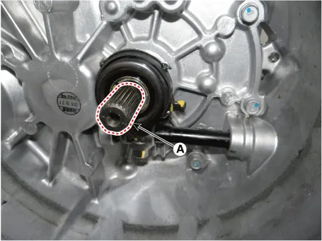
| 7. |
Apply a small amount of multi purpose grease to the input shaft splines (A).
|
| 8. |
Clean the surfaces of the flywheel and pressure plate thoroughly with fine sandpaper or crocus cloth, and make certain that all oil or grease has been removed. |
| 9. |
Install the transaxle assembly. G 1.2 MPI (Refer to Manual Transaxle System - "Manual Transaxle") |
Components and components location Components 1. Union bolt 2. Gasket 3. Tube joint 4. Clutch tube 5. Valve plate 6.
Specifications Specifications Transaxle model M6CF1 Engine type Gasoline 1.4 MPI Manual transalxe oil Capacity 1.
Other information:
Kia Rio 2017-2023 YB Service Manual: Power Door Locks
Components and components location Component Location 1. Driver power window switch 2. Assist power window switch 3 . Body Comtrol Module (BCM) 4 . Tailgate actuator 5 . Door latch lock actuator 6 .
Kia Rio 2017-2023 YB Service Manual: Windshield Wiper/Washer
Components and components location Component Location 1. Windshield wiper arm & blade 2. Wiper & washer switch 3. Windshield washer hose & nozzle 4. Wiper motor & linkage assembly 5. Washer motor 6.
Categories
- Manuals Home
- Kia Rio Owners Manual
- Kia Rio Service Manual
- Maintenance
- Engine Control / Fuel System
- Cooling System
- New on site
- Most important about car
