Kia Rio: Clutch System / Clutch Tube
Components and components location
| Components |
[Gasoline 1.2, 1.4]
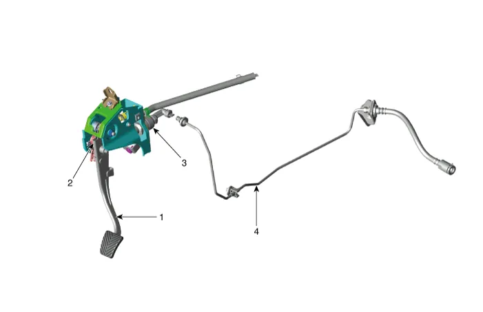
| 1. Clutch pedal assembly 2. Ignition lock and clutch switch |
3. Master cylinder 4. Clutch tube |
[Gasoline 1.0 T-GDI, Diesel 1.4]
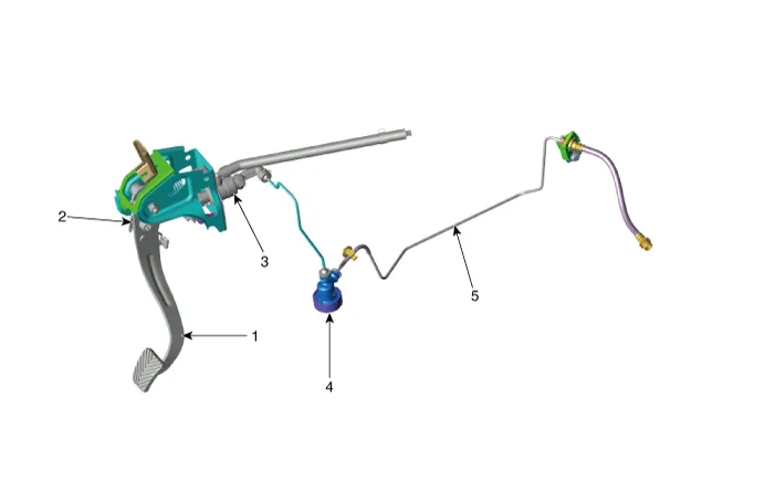
| 1. Clutch pedal assembly 2. Ignition lock and clutch switch 3. Master cylinder |
4. Clutch regulator 5. Clutch tube |
Repair procedures
| Removal |
[Gasoline 1.2, 1.4]
| 1. |
Turn ignition switch OFF and disconnect the negative (-) battery cable. |
| 2. |
Remove the air cleaner assembly. G 1.2 MPI (Refer to Engine Mechanical System - " Air Cleaner") G 1.4 MPI (Refer to Engine Mechanical System - " Air Cleaner") |
| 3. |
Remove the battery and battery tray. G 1.2 MPI (Refer to Engine Electrical System - "Battery") G 1.4 MPI (Refer to Engine Electrical System - "Battery") |
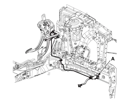
| 4. |
Loosen the clutch tube line bolt (A).
|

| 5. |
Disconnect the clutch tube (A).
|
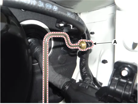
| 6. |
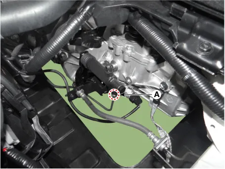
Loosen the clutch tube nut (A)
|
[Gasoline 1.0 T-GDI, Diesel 1.4]
| 1. |
Turn ignition switch OFF and disconnect the negative (-) battery cable |
| 2. |
Remove the air cleaner assembly. D 1.4 U2 TCI (Refer to Engine Mechanical System - " Air Cleaner") G 1.0 T-GDI (Refer to Engine Mechanical System - " Air Cleaner") |
| 3. |
Remove the battery and battery tray. D 1.4 U2 TCI (Refer to Engine Electrical System - "Battery") G 1.0 T-GDI (Refer to Engine Electrical System - "Battery") |
| 4. |
Remove the fuel filter. (Diesel vehicle only) D 1.4 U2 TCI (Refer to Engine Control / Fuel System - "Fuel Filter") |
| 5. |
Remove the ECM. D 1.4 U2 TCI (Refer to Engine Control / Fuel System - "Engine Control Module (ECM)") G 1.0 T-GDI (Refer to Engine Control / Fuel System - "Engine Control Module (ECM)") |
| 6. |
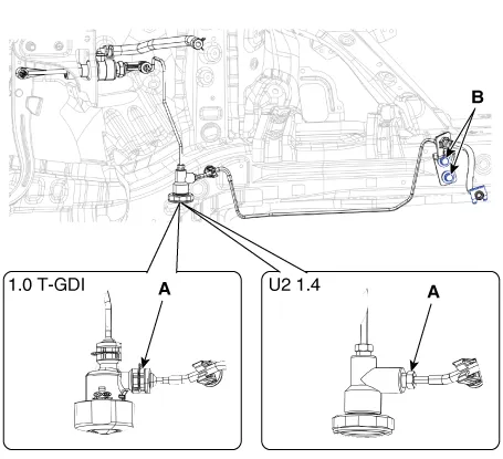
Loosen the clutch tube bracket bolts (B) and then remove the snap pin, flare nut (A) from the regulator.
|
| 7. |
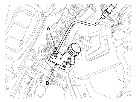
Loosen the release cylinder bolts (A) and then clutch tube nut (B) after removing release cylinder assembly (C).
|
| Installation |
When installing, O-rings of clutch tube should be replaced with a new one. |

| 1. |
Install in the reverse order of removal. |
| 2. |
After be equipped, perform bleeding air procedure after pouring the brake fluid. (Refer to Cltuch Release Cylinder - "Adjustment") |
Components and components location Componets [Gasoline 1.0 T-GDI, Diesel 1.4] 1.. Clutch pedal assembly 2. Ignition lock and clutch switch 3.
Components and components location Components 1. Union bolt 2. Gasket 3. Tube joint 4. Clutch tube 5. Valve plate 6.
Other information:
Kia Rio 2017-2023 YB Service Manual: Smart Key
Repair procedures Smart Key Smart Key Code Saving 1. Connect the DLC cable of KDS/GDS to the data link connector (16 pins) in driver side crash pad lower panel, turn the power on KDS/GDS. 2. Select the vehicle model and then do "Smart key code saving".
Kia Rio 2017-2023 YB Service Manual: Condenser
Repair procedures Inspection 1. Check the condenser fins for clogging and damage. If clogged, clean them with water, and blow them with compressed air. If bent, gently bend them using a screwdriver or pliers. 2.
Categories
- Manuals Home
- Kia Rio Owners Manual
- Kia Rio Service Manual
- Suspension System
- Maintenance Schedule
- Cooling System
- New on site
- Most important about car
