Kia Rio: Smart Key System / Smart Key
Repair procedures
| Smart Key |
Smart Key Code Saving
| 1. |
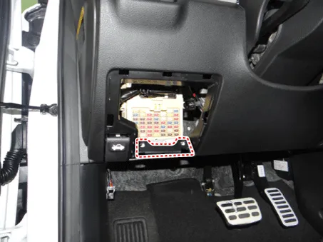
Connect the DLC cable of KDS/GDS to the data link connector (16 pins) in driver side crash pad lower panel, turn the power on KDS/GDS.
|
| 2. |
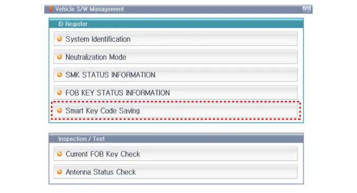
Select the vehicle model and then do "Smart key code saving".
|
| 3. |
After selecting "Smart key teaching" menu, push "Enter" key, then the screen will be shown as below.
|
| 4. |
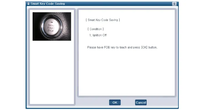
After having the teaching smart key, push "ENTER" key. |
| 5. |
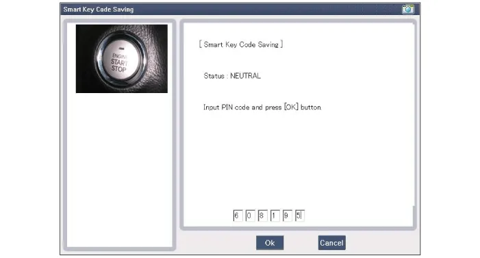
Input the "Pin code" for first key teaching.
|
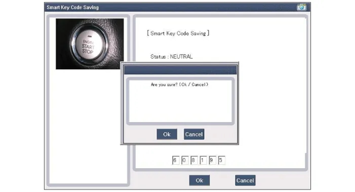
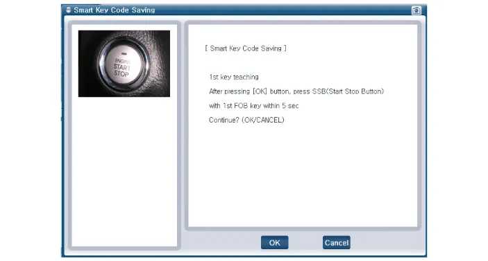
| 6. |
Press the SSB with smart key within 5 sec after pressing "OK".
|
| 7. |
Confirm the message "First key teaching completed".
|
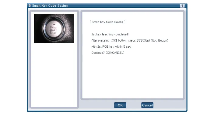
| 8. |
Press the SSB with smart key within 5 sec after pressing "OK".
|
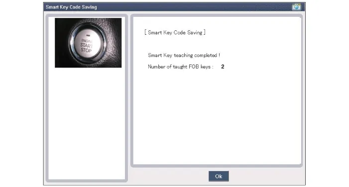
| 9. |
Confirm the message "Second key teaching completed".
|
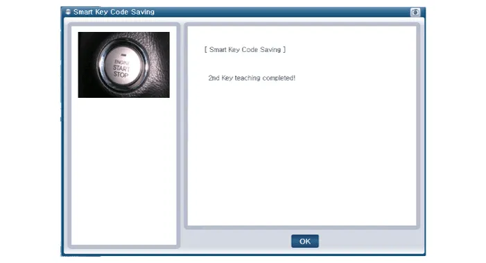
| 10. |
Then the screen will be shown as below when key teaching process is completed.
|
Specifications Specifications Smart Key Unit Items Specification Rated voltage DC 12 V Operating voltage DC 9 - 16 V Operating temperature -31 - 167°F (-35 - 75°C) Load Max.
Components and components location Components Connector Pin Information No. Connector A Connector B Connector C 1 - IGN2 Relay_output Battery (+)_Signal 2 SSB Switch1 signal_input P-CAN (Low) - 3 Driver door outside handle switch_input P-CAN (High) Immobilizer antenna (Power)_output 4 - C-CAN (High) Driver outside handle antenna (Power)_output 5 - C-CAN (Low) Passenger outside handle antenna (Power)_output 6 - SSB Amber illumination_output Bumper antenna (Power)_output 7 RPM Signal_input - Interior antenna 1 (Power)_output 8 Start signal feedback_input SSB Illumination (+)_output Interior antenna 2 (Power)_output 9 IGN2 ESCL Enable_output Interior antenna 3 (Power)_output 10 - Battery (+)_Power - 11 Starter relay_output IGN1 Relay_output - 12 Ground_Power1 ESCL (COM) - 13 SSB Switch2 signal_input EMS (COM) ESCL_Ground (-)_output 14 Assist door outside handle switch_input - Immobilizer antenna (Ground)_output 15 - SSB Illumination (-)_output Driver outside handle antenna (Ground)_output 16 AT : "P" Positon_input MT : Clutch switch_input SSB Illumination (Blue)_output SSB Illumination (Red)_output Passenger outside handle antenna (Ground)_output 17 ESCL Unlock switch_input - Bumper antenna (Ground)_output 18 Wheel speed sensor_input Exterior buzzer_output Interior antenna 1 (Ground)_output 19 ACC Signal_input - Interior antenna 2 (Ground)_output 20 IGN1 ESCL (+)_output Interior antenna 3 (Ground)_output 21 Brake switch_input - 22 ACC Relay_output Ground_Power2 Schematic diagrams Circuit Diagram Repair procedures Removal Put on gloves to prevent hand injuries.
Other information:
Kia Rio 2017-2023 YB Service Manual: Antenna Coil
Repair procedures Removal 1. Disconnect the negative (-) battery terminal. 2. Remove the crash pad lower panel. (Refer to Body - "Crash Pad Lower Panel") 3. Remove the steering column upper and lower shroud panel.
Kia Rio 2017-2023 YB Service Manual: Rear Parking Assist System
Specifications Specification Item Specification Ultrasonic sensor Voltage rating DC 12V Detecting range 11.8 - 47.2 in (30 - 120 cm) Operation voltage DC 9 - 16 V Operation current
Categories
- Manuals Home
- Kia Rio Owners Manual
- Kia Rio Service Manual
- Maintenance
- Clutch System
- Heating,Ventilation, Air Conditioning
- New on site
- Most important about car
