Kia Rio: Clutch System / Clutch Pedal
Components and components location
| Components |
[Gasoline 1.2, 1.4 ]
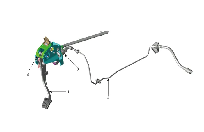
| 1. Clutch pedal assembly 2. Ignition lock and clutch switch |
3. Master cylinder 4. Clutch tube |
[Gasoline 1.0 T-GDI, Diesel 1.4]
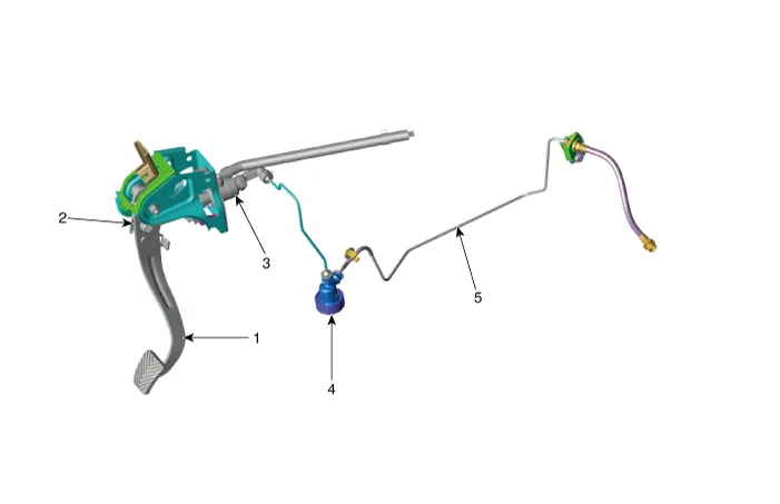
| 1. Clutch pedal assembly 2. Ignition lock and clutch switch 3. Master cylinder |
4. Clutch regulator 5. Clutch tube |
Repair procedures
| Removal |
[Gasoline 1.2,1.4]
| 1. |
Turn ignition switch OFF and disconnect the negative (-) battery cable. |
| 2. |
Remove the crash pad lower panel. (Refer to Body - "Crash Pad Lower Panel") |
| 3. |
Disconnect the ignition lock & clutch switch connector.
|

| 4. |
Remove the push rod.
|
| 5. |
Remove the air cleaner assembly. G 1.2 MPI (Refer to Engine Mechanical System - " Air Cleaner") G 1.4 MPI (Refer to Engine Mechanical System - " Air Cleaner") |
| 6. |
Remove the battery and battery tray. G 1.2 MPI (Refer to Engine Electrical System - "Battery") G 1.4 MPI (Refer to Engine Electrical System - "Battery") |
| 7. |
Remove the ECM. G 1.2 MPI (Refer to Engine Control / Fuel System - Engine Control Module (ECM)") G 1.4 MPI (Refer to Engine Control / Fuel System - Engine Control Module (ECM)") |
| 8. |
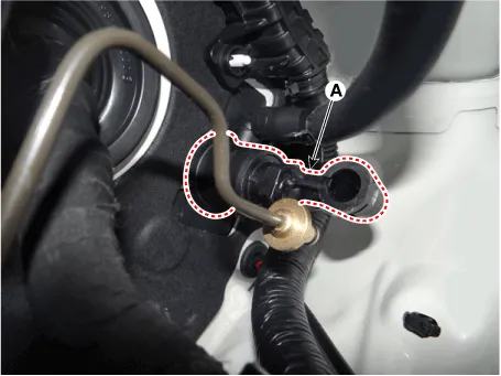
Disconnect the reservoir hose (A) and clutch tube (B) from the clutch master cylinder.
|

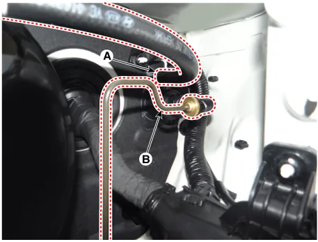
| 9. |
Remove the clutch master cylinder (A) by turning it clockwise.
|
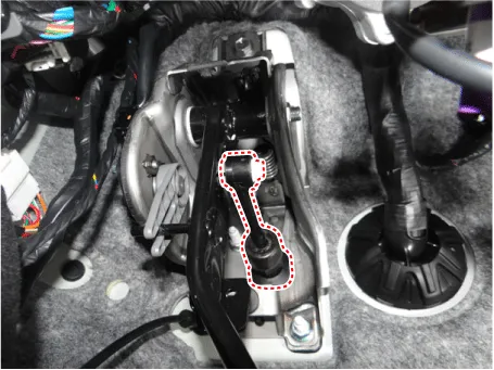
| 10. |
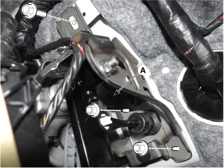
Loosen the clutch pedal mounting nuts and bolt and then remove the clutch pedal (A)
|
[Gasoline 1.0 T-GDI, Diesel 1.4]
| 1. |
Turn ignition switch OFF and disconnect the negative (-) battery cable |
| 2. |
Remove the crash pad lower panel. (Refer to Body - "Crash Pad Lower Panel") |
| 3. |
Disconnect the ignition lock & clutch switch connector.
|
| 4. |
Remove the push rod.
|
| 5. |
Remove the air cleaner assembly. D 1.4 U2 TCI (Refer to Engine Mechanical System - " Air Cleaner") G 1.0 T-GDI (Refer to Engine Mechanical System - " Air Cleaner") |
| 6. |
Remove the battery and tray. D 1.4 U2 TCI (Refer to Engine Electrical System - "Battery") G 1.0 T-GDI (Refer to Engine Electrical System - "Battery") |
| 7. |
Remove the fuel filter. (Diesel vehicle only) D 1.4 U2 TCI (Refer to Engine Control / Fuel System - "Fuel Filter") |
| 8. |
Remove the ECM. D 1.4 U2 TCI (Refer to Engine Control / Fuel System - "Engine Control Module (ECM)") G 1.0 T-GDI (Refer to Engine Control / Fuel System - "Engine Control Module (ECM)") |
| 9. |
Disconnect the reservoir hose (A) and clutch tube (B) from the clutch master cylinder.
|
| 10. |
Remove the clutch master cylinder (A) by turning it clockwise.
|
| 11. |
Loosen the clutch pedal mounting nuts and bolt and then remove the clutch pedal (A).
|
| Installation |
| 1. |
Install in the reverse order of removal. |
| 2. |
After be equipped, perform bleeding air procedure in clutch release cylinder after pouring the brake fluid. (Refer to Cltuch Release Cylinder - "Adjustment") |
Specifications Specifications Item Specifications Working voltage DC 12.5V Operating force Initial position : 0.
Components and components location Components [Gasoline 1.2, 1.4 ] 1. Clutch pedal assembly 2. Ignition lock and clutch switch 3.
Other information:
Kia Rio 2017-2023 YB Service Manual: Turn Signal Lamp
Repair procedures Removal Door Mirror Turn Signal Lamp 1. Disconnect the negative (-) battery terminal. 2. Remove the mirror (A) from the mirror holder. Be careful not to damag
Kia Rio 2017-2023 YB Service Manual: Ambient Temperature Sensor
Description and operation Description The ambient temperature sensor is located at the front of the condenser and detects ambient air temperature. It is a negative type thermistor; resistance will increase with lower temperature, and decrease with higher temperature.
Categories
- Manuals Home
- Kia Rio Owners Manual
- Kia Rio Service Manual
- Maintenance
- Emission Control System
- General Information
- New on site
- Most important about car
