Kia Rio: Motor Driven Power Steering / MDPS Column and Housing
Repair procedures
| Removal |
| 1. |
Remove the steering column and shaft assembly. (Refer to Motor Driven Power Steering - "Steering Column and Shaft") |
| 2. |
Remove the MDPS control unit. (Refer to Motor Driven Power Steering - "MDPS Control Unit") |
| 3. |
Remove the MDPS motor. (Refer to Motor Driven Power Steering - "MDPS Motor") |
| Installation |
| 1. |
Install in the reverse order of removal. |
| 2. |
Perform the "Steering Angle Sensor (SAS) Calibration" and "Set the steering feel torque to zero". |
| 3. |
Perform the "EPS Type Recognition". |
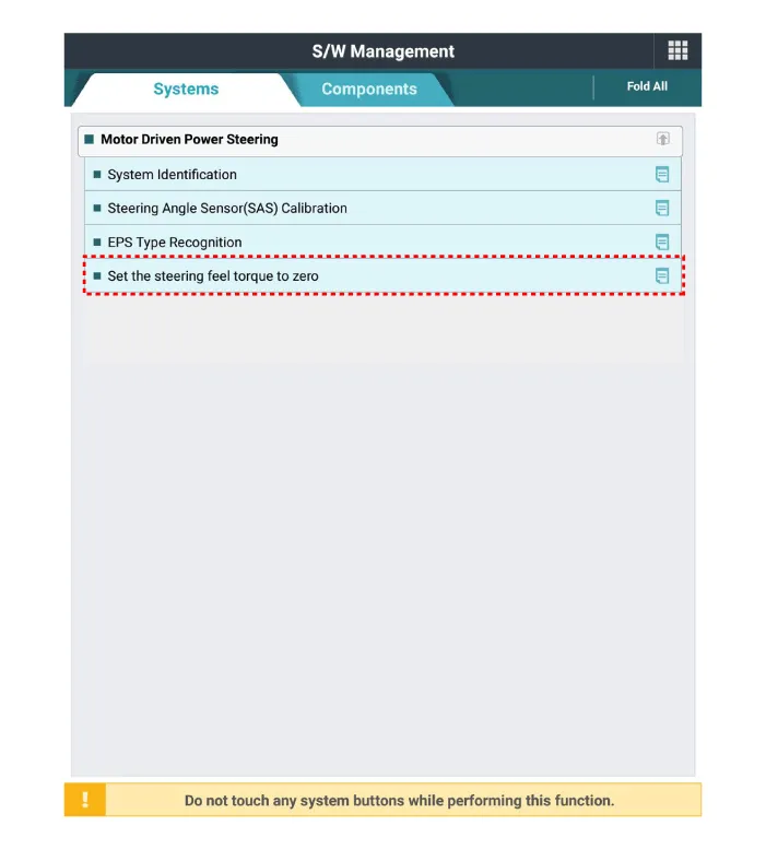
| Diagnosis with KDS |
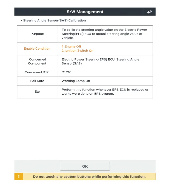
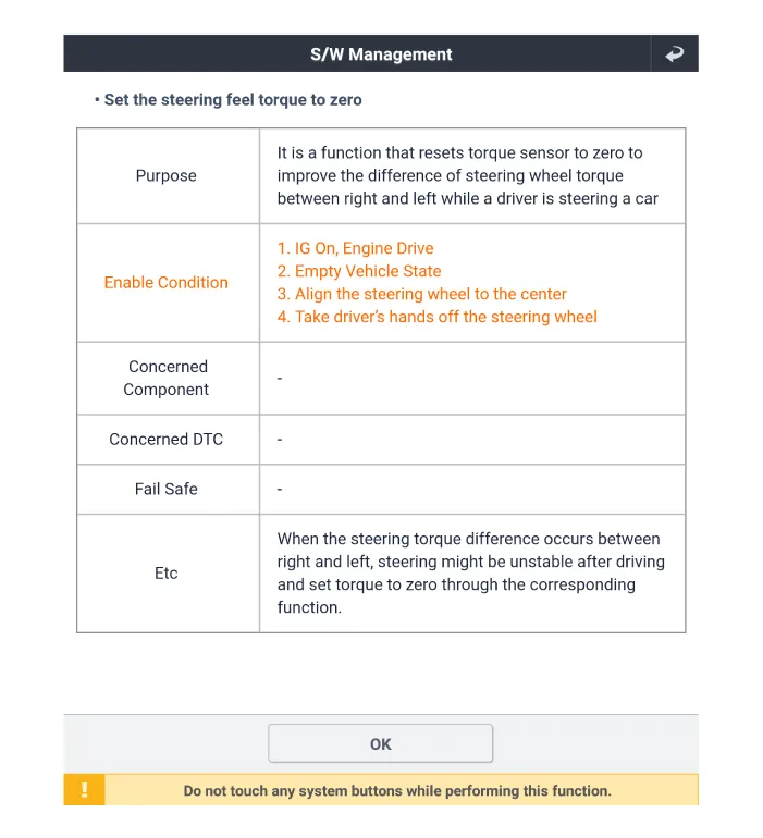
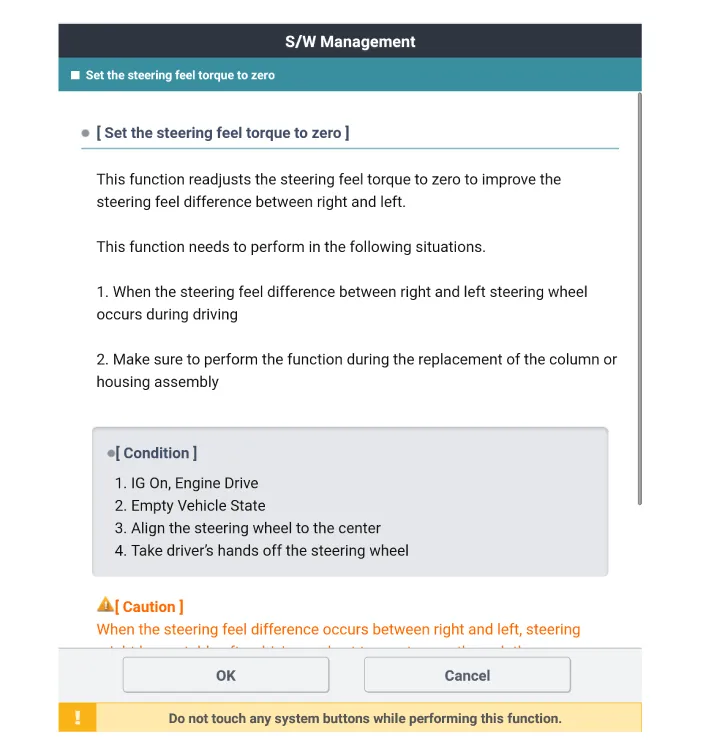
Steering Angle Sensor (SAS) Calibration and Set the steering feel torque to zero
|

| 1. |
Connect self-diagnosis connector (16pins) located under the driver side crash pad to self-diagnosis device, and then turn the self-diagnosis device after key is ON. |
| 2. |
Select the "vehicle model" and "Motor Driven Power Steering" on KDS vehicle selection screen. |
| 3. |
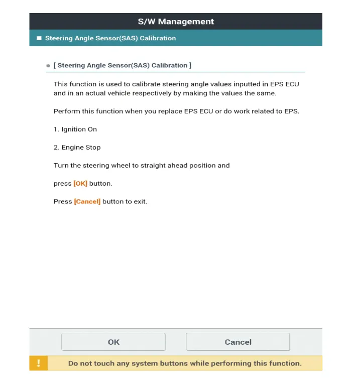
Select the "Steering Angle Sensor (SAS) Calibration" on KDS screen, then select OK. |
| 4. |
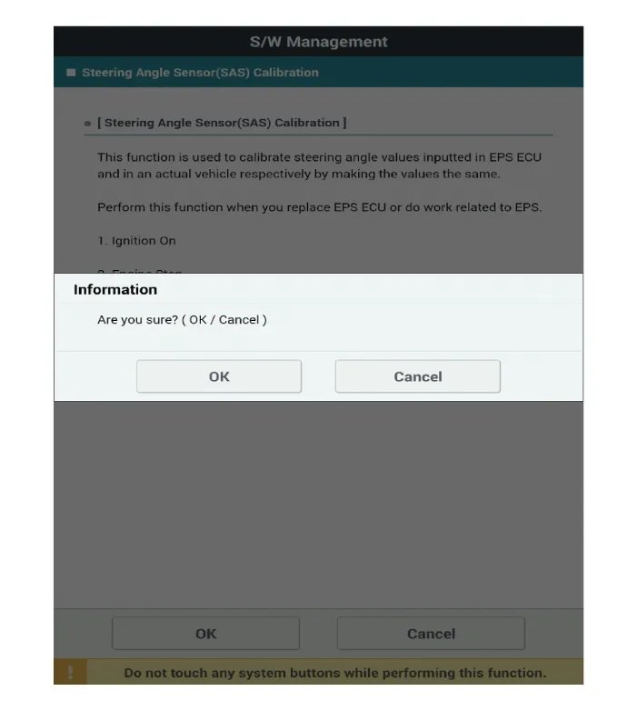
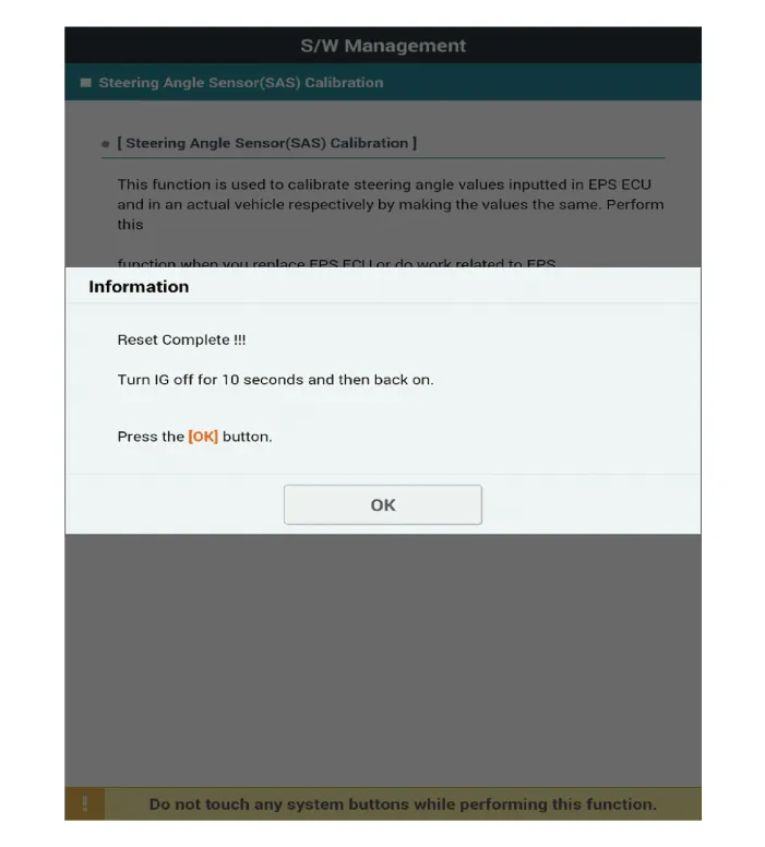
Proceed with the test according to the screen instructions.
|

| 5. |
Select the "Set the steering feel torque to zero" on KDS screen, then select OK. |
| 6. |
Proceed with the test according to the screen instructions.
|

| 7. |
Remove the DTC. |
| 8. |
Turn off the IG switch and wait for 10 seconds or more before starting the engine. And then make sure that MDPS works properly. |
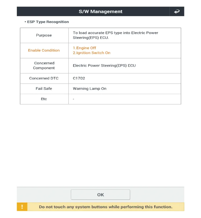
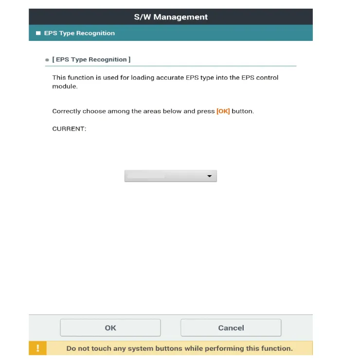
EPS Type Recognition
|
| 1. |
Connect self-diagnosis connector (16pins) located under the driver side crash pad to self-diagnosis device, and then turn the self-diagnosis device after key is ON. |
| 2. |
Select the "vehicle model" and "Motor Driven Power Steering" on KDS vehicle selection screen. |
| 3. |
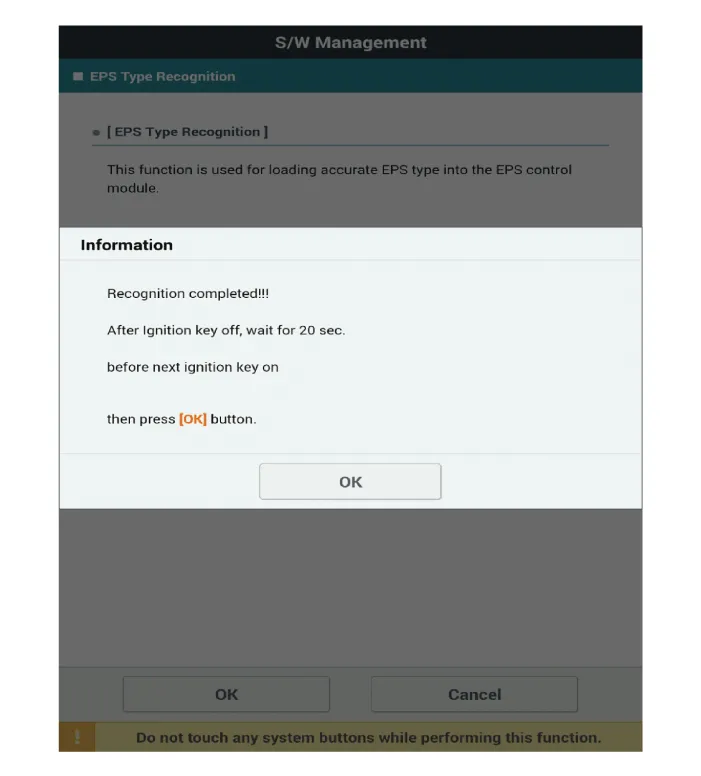
Select the "EPS Type Recognition" on KDS screen, then select OK. |
| 4. |
Proceed with the test according to the screen instructions.
|

| 5. |
Remove the DTC. |
| 6. |
Turn off the IG switch and wait for 10 seconds or more before starting the engine. And then make sure that MDPS works properly. |
Repair procedures Removal 1. Disconnect the battery negative cable. 2. Remove the crash pad lower panel.
Repair procedures Removal 1. Disconnect the battery negative cable. 2. Turn the steering wheel so that the front wheels are facing straight ahead.
Other information:
Kia Rio 2017-2023 YB Service Manual: Overhead Console Lamp
Repair procedures Inspection 1. Remove the overhead console lamp assembly then check for continuity between terminals. If the continuity is not as specified, replace the map lamp switch. Removal 1.
Kia Rio 2017-2023 YB Service Manual: Sunroof Switch
Components and components location Components Repair procedures Inspection 1. Disconnect the negative (-) battery terminal. 2. Open the sunglass case cover from the overhead console and remove the 2 screws holding the overhead console.
Categories
- Manuals Home
- Kia Rio Owners Manual
- Kia Rio Service Manual
- Maintenance Schedule
- Cooling System
- Suspension System
- New on site
- Most important about car
