Kia Rio: Body Electrical System / Ignition Switch
Repair procedures
| Inspection |
| 1. |
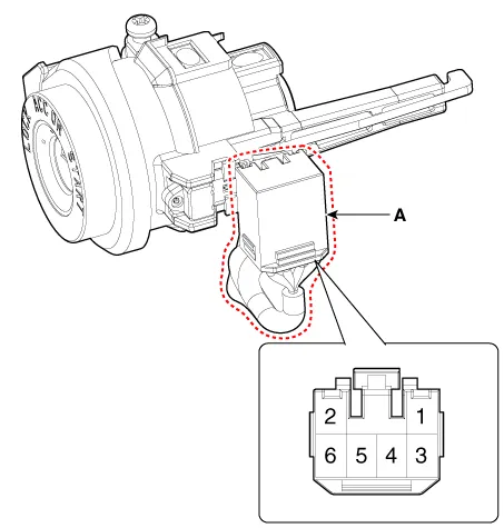
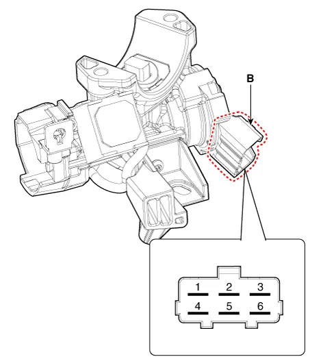
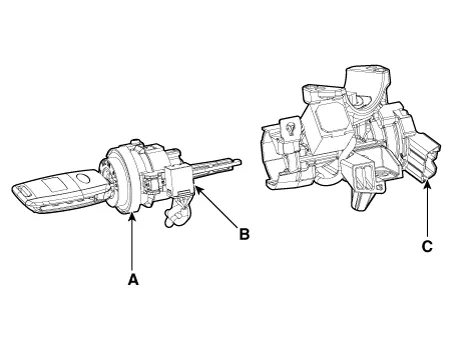
Disconnect the key warning switch connector (A) and ignition switch connector (B) from the steering column.
|
| 2. |
Check for continuity between the terminals. |
| 3. |
If continuity is not specified, replace the switch.
|

| Removal |
| 1. |
Disconnect the negative (-) battery terminal. |
| 2. |
Remove the crash pad lower panel. (Refer to Body - "Crash Pad Lower Panel") |
| 3. |
Remove the steering column upper and lower shroud panel. (Refer to Body - "Steering Column Shroud Panel") |
| 4. |
Remove the multifunction switch. (Refer to Body Electrical System - "Multifunction Switch") |
| 5. |
Remove the ignition switch connector (A) and key warning / immobilizer connector (B).
|

| 6. |
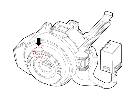
Insert key and turn it to ACC position.
|
| 7. |
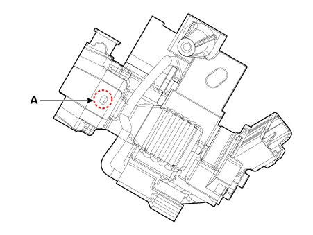
Pushing lock pin (A) with the awl.
|
| 8. |
Remove the key lock cylinder (A).
|
| 9. |
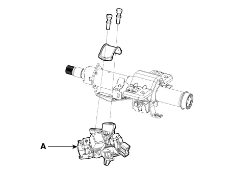
Remove the ignition switch (A) after loosening the mounting bolts.
|
| Installation |
|

| 1. |
Install the ignition switch. |
| 2. |
Install the key lock cylinder. |
| 3. |
Connect the ignition switch connector and key warning / immobilizer connector. |
| 4. |
Install the multifunction switch. |
| 5. |
Install the steering column upper and lower shroud panel. |
| 6. |
Install the crash pad lower panel. |
| 7. |
Connect the negative (-) battery terminal. |
Components and components location Component Location 1. Horn switch 2. Horn relay 3. Horn 4. Clock spring Repair procedures Removal 1.
Schematic diagrams Circuit Diaram Description and operation Description The immobilizer system will disable the vehicle unless the proper ignition key is used, in addition to the currently available anti-theft systems such as car alarms, the immobilizer system aims to drastically reduce the rate of auto theft.
Other information:
Kia Rio 2017-2023 YB Service Manual: Indicators And Gauges
Troubleshooting Troubleshooting Error Item Failure symptom Inspection items Detailed inspections Relevant Parts/ Components Screen display LCD screen does not turn on 1) Connector attachments
Kia Rio 2017-2023 YB Service Manual: Rear Glass Defogger Printed Heater
Repair procedures Inspection • Wrap tin foil around the end of the voltmeter test lead to prevent damaging the heater line. Apply pressure on the tin foil with hand and move the tin foil along the grid line to check for open circ
Categories
- Manuals Home
- Kia Rio Owners Manual
- Kia Rio Service Manual
- Timing Chain
- Body (Interior and Exterior)
- Body Electrical System
- New on site
- Most important about car
