Kia Rio: Controller / Heater & A/C Control Unit (MANUAL)
Components and components location
| Components |
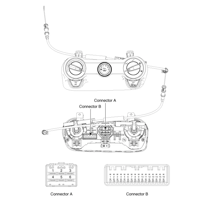
Connector pin function
|
NO. |
Connector A |
Connector B |
|
1 |
Low |
Battery |
|
2 |
Common |
ISG Battery |
|
3 |
High |
Illumination (+) |
|
4 |
Middle_LOW |
Sensor (+5V) |
|
5 |
Middle_High |
⁻ |
|
6 |
High |
Intake actuator Feedback |
|
7 |
|
Evaporator sensor (+) |
|
8 |
Ambient sensor (+) |
|
|
9 |
⁻ |
|
|
10 |
⁻ |
|
|
11 |
Intake actuator (FRE) |
|
|
12 |
Intake actuator (REC) |
|
|
13 |
HTD |
|
|
14 |
Rear defog switch |
|
|
15 |
Blower on signal to common |
|
|
16 |
Illumination (-) |
|
|
17 |
IGN2 |
|
|
18 |
IGN1 |
|
|
19 |
⁻ |
|
|
20 |
Max blower on signal |
|
|
21 |
PTC relay 3 |
|
|
22 |
PTC relay 2 |
|
|
23 |
PTC on signal |
|
|
24 |
Detent out (-) |
|
|
25 |
⁻ |
|
|
26 |
Chassis_CAN (High) |
|
|
27 |
Chassis_CAN (Low) |
|
|
28 |
⁻ |
|
|
29 |
ECV (+) |
|
|
30 |
ECV (-) |
|
|
31 |
Sensor ground |
|
|
32 |
Ground |
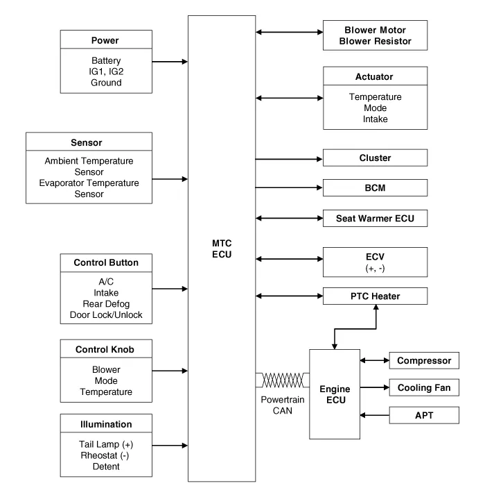
Schematic diagrams
| Schematic Diagram |
Repair procedures
| Replacement |
| 1. |
Disconnect the negative (-) battery terminal. |
| 2. |
Remove the crash pad lower panel. (Refer to Body - "Crash Pad Lower Panel") |
| 3. |
Remove the audio unit. (Refer to Body Electrical System - "Audio Unit") |
| 4. |
Remove the glove box. (Refer to Crash Pad - "Glove Box Housing") |
| 5. |
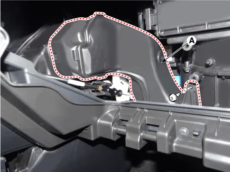
Remove the driver's side shower duct (A) after loosening the screw.
|
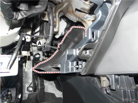
| 6. |
Disconnect the mode control cable (A).
|
| 7. |
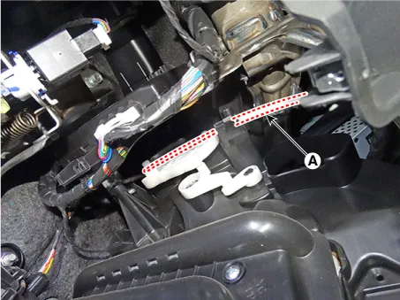
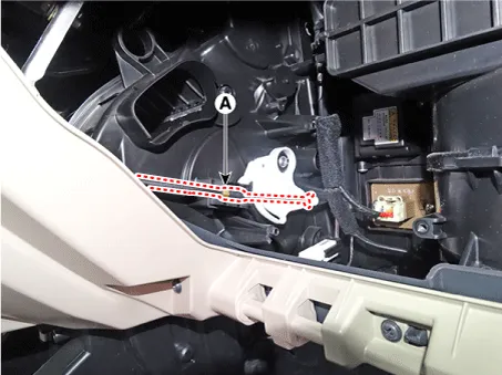
Remove the passenger's side shower duct (A) after loosening the screw.
|
| 8. |
Disconnect the temperature control cable (A).
|
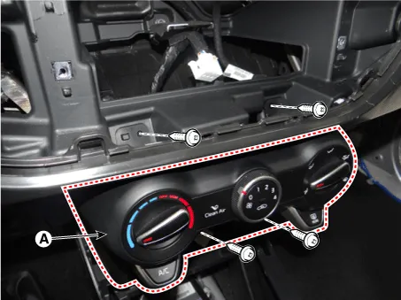
| 9. |
After loosening the mounting screws, remove the A/C & heater controller unit (A).
|
| 10. |
Disconnect the A/C & heater controller connectors (A).
|
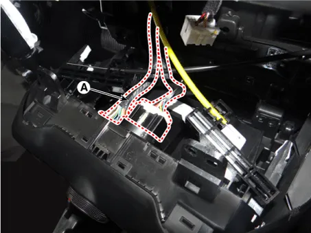
| 11. |
To install, reverse the removal procedure. |
Components and components location Components Connector Pin Function No. Connector A Connector B 1 Battery ⁻ 2 ISG battery (+) ⁻ 3 Illumination (+) ⁻ 4 Sensor (REF) (+) Defogging actuator Feedback 5 Mode control actuator Feedback Defogging actuator (Open) 6 Temperature control actuator Feedback Defogging actuator (Close) 7 Intake actuator Feedback ⁻ 8 Evapoerator sensor (+) ⁻ 9 Ambient sensor (+) ⁻ 10 Mode control actuator (VENT) ⁻ 11 Mode control actuator (DEF) Defog current 12 Temperature control actuator (COOL) Defog temperature 13 Temperature control actuator (WARM) Defog sck 14 Intake actuator (FRE) Defog data 15 Intake actuator (REC) ⁻ 16 HTD Ground 17 Rear defog switch 18 ⁻ 19 ⁻ 20 Illumination (-) 21 IGN2 22 IGN1 23 Blower motor (+) 24 Photo sensor (-) 25 ⁻ 26 ⁻ 27 ⁻ 28 PTC relay 3 29 PTC relay 2 30 PTC on signal 31 Detent out (-) 32 ⁻ 33 Chassis_CAN (High) 34 Chassis_CAN (Low) 35 FET (Drain hose Feedback) 36 FET (Gate) 37 ECV (+) 38 ECV (-) 39 Sensor ground 40 Ground Schematic diagrams Schematic Diagrams Repair procedures Self Diagnosis 1.
Other information:
Kia Rio 2017-2023 YB Service Manual: Immobilizer Control Unit
Repair procedures Removal 1. Disconnect the negative (-) battery terminal. 2. Remove the main crash pad assembly. (Refer to Body - "Main Crash Pad Assembly") 3. Disconnect the connector of the immobilizer unit and then remove the immobilizer unit (A) after
Kia Rio 2017-2023 YB Service Manual: Climate Control Air Filtar
Description and operation Description The climate control air filter is located in the bower unit. It eliminates foreign materials and odor. The particle filter performs a role as an odor filter as well as a conventional dust filter to ensure comfortable interior environment.
Categories
- Manuals Home
- Kia Rio Owners Manual
- Kia Rio Service Manual
- Heating,Ventilation, Air Conditioning
- Engine Oil and Filter
- Emission Control System
- New on site
- Most important about car
