Kia Rio: Engine Control / Fuel System / Fuel Delivery System
Components and components location
| Components Location |
| Fuel Tank & Filler-Neck Assembly |

| 1. Fuel Tank 2. Fuel Pump 3 Fuel Pump Plate Cover 4. Fuel Filler Hose 5. Leveling Tube 6. Vapor Tube (Canister → Intake Manifold) |
7. Vapor Hose (Canister → Fuel
Tank) 8. Vapor Hose (Canister → Air Filter) 9. Vapor Hose (Air Filter → Atmosphere) 10. Fuel Tank Band 11. Filler-Neck Assembly |
| Fuel Pump |
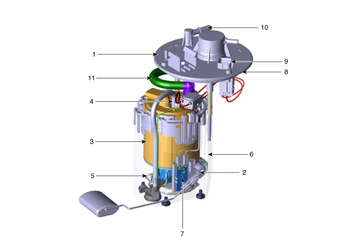
| 1. Head Assembly 2. Fuel Pressure Regulator 3. Fuel Filter 4. Fuel Pump Motor 5. Fre-Filter 6. Reservoir Cup |
7. Fuel Sender 8. Fuel Pump Plate Packing 9. Fuel Pump Motor & Fuel Sender Connector 10. Fuel Feed Port 11. Fuel Feed Tube |
Fuel pressure test (low pressure system)
| Fuel Pressure Test (Low pressure system) |
| 1. |
Release the residual pressure in fuel line. (Refer to “Release Residual Pressure in Fuel Line” in this group).
|

| 2. |
Install the Special Service Tool (SST).
|

| 3. |
Inspect fuel leakage on connections among the low fuel feed tube, the low pressure inlet of high pressure fuel pump, and the SST components with IG ON. |
| 4. |
Measure Fuel Pressure.
|

| 5. |
Release the residual pressure in fuel line (Refer to “Release Residual Pressure in Fuel Line”). |
| 6. |
Test End
|
Release residual pressure in fuel line
| Release Residual Pressure in Fuel Line |
There may be some residual pressure even after “Release Residual Pressure in Fuel Line” work, so cover the hose connection with a shop towel to prevent residual fuel from spilling out before disconnecting any fuel connection. |
| 1. |
Turn the ignition switch OFF and disconnect the battery (-) terminal. |
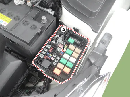
| 2. |
Remove the fuel pump fuse (A).
|
| 3. |
Connect the battery negative (-) terminal. |
| 4. |
Start the engine and let idle. |
| 5. |
Turn the ignition switch OFF after the engine has stopped on its own. |
| 6. |
Disconnect the battery negative (-) terminal, and then install the fuel pump fuse (A). |
| 7. |
Connect the battery negative (-) terminal. |
| 8. |
Delete the Diagnostic Trouble Code (DTC) related the fuel pump fuse with the KDS/GDS. |
- Fuel Tank
- Fuel Pump
- Fuel Filter
- Fuel Pump Motor
- Fuel Sender
- Fuel Pressure Regulator
- Filler-Neck Assembly
- Fuel Line
- Delivery Pipe
Components and components location Components Description and operation Description The ISG OFF switch on the floor console can be used to deactivate the ISG function.
Repair procedures Removal 1. Release the residual pressure in fuel line. (Refer to Delivery System - "Release Residual Pressure in Fuel Line”) 2.
Other information:
Kia Rio 2017-2023 YB Service Manual: Instrument Cluster
Components and components location Components [Standard Type ("3.5")] [Supervision Type ("3.5")] Connector Pin Information Connector A No.
Kia Rio 2017-2023 YB Service Manual: Lane Departure Warning System (LDWS)
Components and components location Components 1. LDWS ON/OFF switch 2. Instrument cluster 3. LDWS unit (MFC) ※ MFC : Multi Function Camera – Function : LDWS, HBA, AEB Description and operation Description System block diagram Components of LDWS
Categories
- Manuals Home
- Kia Rio Owners Manual
- Kia Rio Service Manual
- Clutch System
- Maintenance
- Heating,Ventilation, Air Conditioning
- New on site
- Most important about car
