
Kia Rio: Fuel Delivery System / Fuel Sender
Repair procedures
| Removal |
| 1. |
Remove the fuel pump. (Refer to Fuel Delivery System - "Fuel Pump") |
| 2. |
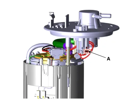
Disconnect the fuel sender connector (A).
|
| 3. |
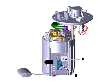
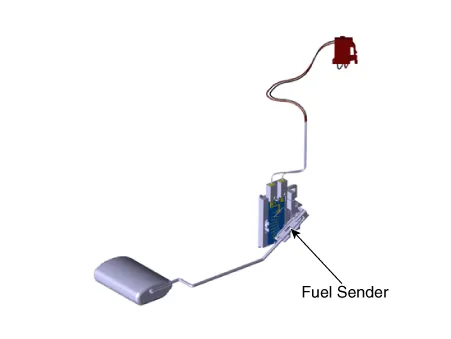
Press the fixing hook (A) with a driver and then remove fuel sender in the arrow direction.
|
| Inspection |
| 1. |
Turn the ignition switch OFF, and then remove battery (-) cable. |
| 2. |
Remove the fuel pump assembly. |
| 3. |
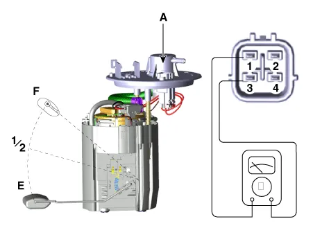
Using an ohmmeter, measure the resistance between terminals 1 and 3 of sender connector (A) at each float level.
|
| 4. |
Also, check that the resistance changes smoothly when the float moves from "E" to "F".
|
| Installation |
| 1. |
Install in the reverse order of removal. |
Repair procedures Removal 1. Remove the fuel pump. (Refer to Fuel Delivery System - "Fuel Pump") 2.
Repair procedures Removal 1. Remove the fuel pump. (Refer to Fuel Delivery System - "Fuel Pump") 2.
Other information:
Kia Rio 2017-2023 YB Service Manual: Power Door Lock Switch
Repair procedures Removal • When removing with a flat-tip screwdriver or remover, wrap protective tape around the tools to prevent damage to components.
Kia Rio 2017-2023 YB Service Manual: Rain Sensor
Components and components location Components Schematic diagrams Circuit Diagram Description and operation Description Integrated Rain Sensor Integrated rain sensor (A) controls three systems: front wiper, auto-light, and central air conditioner.
Categories
- Manuals Home
- Kia Rio Owners Manual
- Kia Rio Service Manual
- Cooling System
- Engine Control / Fuel System
- Engine Mechanical System
- New on site
- Most important about car
