
Kia Rio: Fuel Delivery System / Fuel Pressure Regulator
Repair procedures
| Removal |
| 1. |
Remove the fuel pump. (Refer to Fuel Delivery System - "Fuel Pump") |
| 2. |
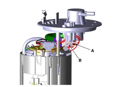
Disconnect the fuel pump motor connector (A) and fuel sender connector (B).
|
| 3. |
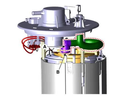
Disconnect the fuel feed tube quick-connector (A) after removing the fixing clip (B).
|
| 4. |
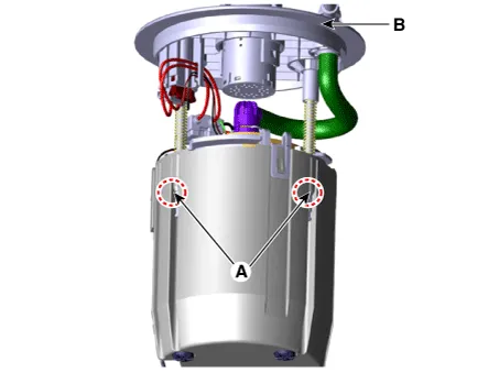
Remove the cushion pipe fixing clip (A), and then separate the head assembly (B) from reservoir cup.
|
| 5. |
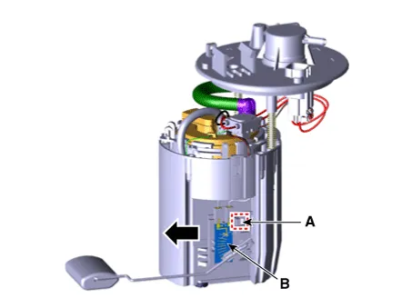
Press the fixing hook (A) with a driver and then remove fuel sender in the arrow direction.
|
| 6. |
Remove the reservoir-cup (B) after releasing the fixing hooks (A).
|
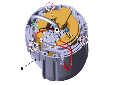
| 7. |
Remove the fuel pressure regulator fixing clip (A).
|
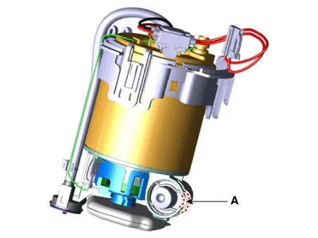
| 8. |
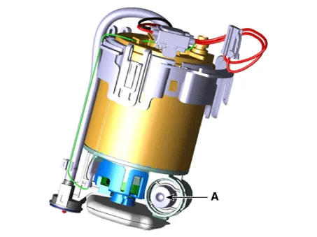
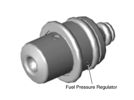
Remove the fuel pressure regulator (A) from the fuel filter.
|
| Installation |
| 1. |
Install in the reverse order of removal. |
Repair procedures Removal 1. Remove the fuel pump. (Refer to Fuel Delivery System - "Fuel Pump") 2.
Repair procedures Removal 1. Open the fuel filler door and then remove the filler-neck mounting bolts (A). Filler-neck assembly mounting bolt: 7.
Other information:
Kia Rio 2017-2023 YB Service Manual: Rear Glass Defogger Switch
Repair procedures Inspection 1. In the body electrical system, failure can be quickly diagnosed by using the vehicle diagnostic system (KDS/GDS). The diagnostic system (KDS/GDS) provides the following information. (1) Self diagnosis : Checking failure and code number (DTC)
Kia Rio 2017-2023 YB Service Manual: Photo Sensor (FATC only)
Description and operation Description The photo sensor is located at the center of defrost nozzles. The photo sensor contains a photovoltaic (sensitive to sunlight) diode. The solar radiation received by its light receiving portion, generates an electromotive force in proportion to the amount of radiation received which is tran
Categories
- Manuals Home
- Kia Rio Owners Manual
- Kia Rio Service Manual
- Engine Mechanical System
- Engine Electrical System
- Maintenance
- New on site
- Most important about car
