Kia Rio: Fuel Delivery System / Fuel Pump
Repair procedures
| Inspection |
[Fuel pump]
| 1. |
Turn ignition switch OFF and disconnect the negative (-)battery cable. |
| 2. |
Remove the fuel pump assembly. |
| 3. |
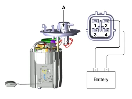
Check motor operation by fuel pump connector (A) connecting power(No.2) and ground(No.4)
|
[Fuel sender]
| 1. |
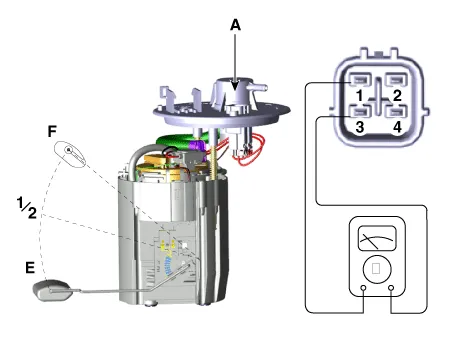
Using an ohmmeter, measure the resistance between terminals 1 and 3 of sender connector (A) at each float level.
|
| 2. |
Also, check that the resistance changes smoothly when the float moves from "E" to "F".
|
| Removal |
| 1. |
Release the residual pressure in fuel line. (Refer to Delivery System - “Release Residual Pressure in Fuel Line”) |
| 2. |
Remove the rear seat. (Refer to Body - "Rear Seat Assembly") |
| 3. |
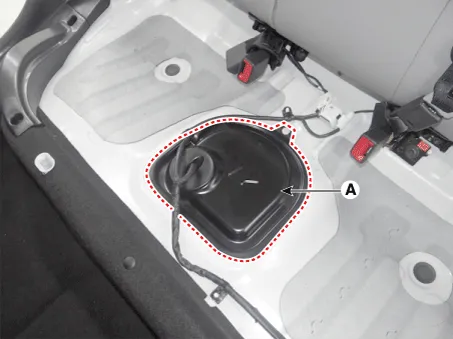
Remove the fuel pump service cover (A).
|
| 4. |
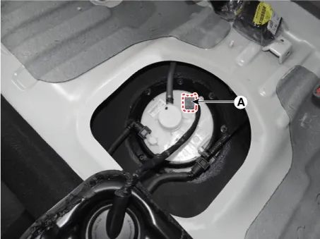
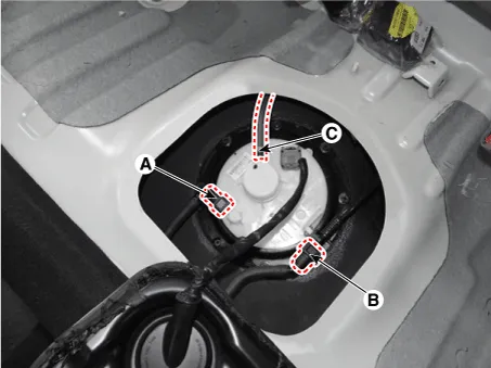
Disconnect the fuel pump connector (A).
|
| 5. |
Disconnect the fuel feed tube quick-connector (A), the vapor tube quick-connector (B) and the vapor hose (C).
|
| 6. |
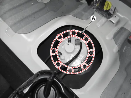
Remove the plate cover (A) after removing the installation bolts and then remove the fuel pump from the fuel tank.
|
| Installation |
| 1. |
Installation is reverse of removal.
|

Repair procedures Removal 1. Release the residual pressure in fuel line. (Refer to Delivery System - "Release Residual Pressure in Fuel Line”) 2.
Repair procedures Removal 1. Remove the fuel pump. (Refer to Fuel Delivery System - "Fuel Pump") 2.
Other information:
Kia Rio 2017-2023 YB Service Manual: Rear Washer Switch
Repair procedures Inspection Multifunction Switch Inspection [BCM Type] 1. Check for continuity between the terminals in each switch position as shown below. [Left Handle Drive] Switch Switch position Switch terminal
Kia Rio 2017-2023 YB Service Manual: Heater & A/C Control Unit (MANUAL)
Components and components location Components Connector pin function NO. Connector A Connector B 1 Low Battery 2 Common ISG Battery 3 High Illumination (+)
Categories
- Manuals Home
- Kia Rio Owners Manual
- Kia Rio Service Manual
- Body (Interior and Exterior)
- Cooling System
- Engine Electrical System
- New on site
- Most important about car
