
Kia Rio: Body (Interior and Exterior) / Crash Pad
Components and components location
| Components |
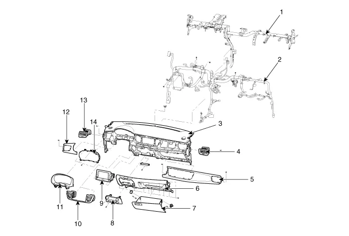
| 1. Cowl cross bar assembly
2. Main wiring harness 3. Main crash pad assembly 4. Side air vent duct assembly [RH] 5. Crash pad passenger side panel assembly 6. Crash pad center lower panel assembly 7. Glove box housing assembly |
8. Heater control assembly
9. Audio unit assembly 10. Center fascia panel assembly 11. Cluster fascia upper panel assembly 12. Crash pad driver side panel assembly 13. Side air vant duct assembly [LH] 14. Instrument cluster assembly |
- Cluster Fascia Panel
- Center Fascia Panel
- Crash Pad Garnish [RH]
- Crash Pad Lower Panel
- Glove Box Housing
- Steering Column Shroud Panel
- Crach Pad Center Panel
- Main Crash Pad Assembly
- Cowl Cross Bar Assembly
Components and components location Component Location 1. Cowl top cover Repair procedures Replacement Put on gloves to protect your hands.
Components and components location Component Location 1. Cluster fascia panel Repair procedures Replacement Put on gloves to protect your hands.
Other information:
Kia Rio 2017-2023 YB Service Manual: Rear Washer Switch
Repair procedures Inspection Multifunction Switch Inspection [BCM Type] 1. Check for continuity between the terminals in each switch position as shown below. [Left Handle Drive] Switch Switch position Switch terminal
Kia Rio 2017-2023 YB Service Manual: Compressor
Description and operation Description The compressor is the power unit of the A/C system. It is located on the side of engine block and driven by a V-belt of engine. The compressor changes the low pressure and low temperature refrigerant gas into the high pressure and high temperature refrigerant gas.
Categories
- Manuals Home
- Kia Rio Owners Manual
- Kia Rio Service Manual
- Restraint
- Motor Driven Power Steering
- Suspension System
- New on site
- Most important about car
