Kia Rio: Crash Pad / Main Crash Pad Assembly
Components and components location
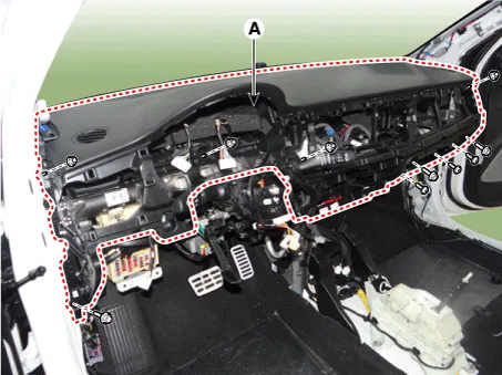
| Component Location |
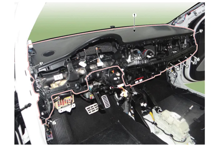
| 1. Main crash pad assembly
|
Repair procedures
| Replacement |
Put on gloves to protect your hands. |

|

| 1. |
Disconnect the negative (-) battery terminal. |
| 2. |
Remove the front seat. (Refer to Front Seat - "Front Seat Assembly") |
| 3. |
Remove the floor console assembly. (Refer to Floor Console - "Floor Console Assembly") |
| 4. |
Remove the cluster fascia panel. (Refer to Crash Pad - "Cluster Fascia Panel") |
| 5. |
Remove the crash pad lower panel [LH]. (Refer to Crash Pad - "Crash Pad Lower Panel") |
| 6. |
Remove the center fascia panel. (Refer to Crash Pad - "Center Fascia Panel") |
| 7. |
Remove the heater control unit. (Refer to Heating,Ventilation And Air Conditioning - "Heater & A/C Control Unit (FATC)") |
| 8. |
Remove the crash pad center lower panel. (Refer to Crash Pad - "Crach Pad Center Panel") |
| 9. |
Remove the steering wheel. (Refer to Steering System - "Steering Wheel") |
| 10. |
Remove the steering column shroud lower panel. (Refer to Crash Pad - "Steering Column Shroud Panel") |
| 11. |
Remove the front pillar trim. (Refer to Interior Trim - "Front Pillar Trim") |
| 12. |
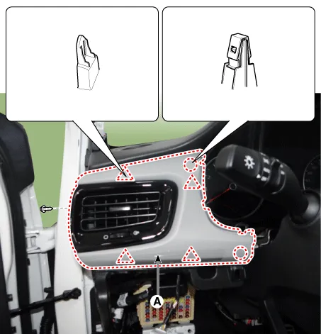
Remove the crash pad driver side panel & air vent duct (A).
|
| 13. |
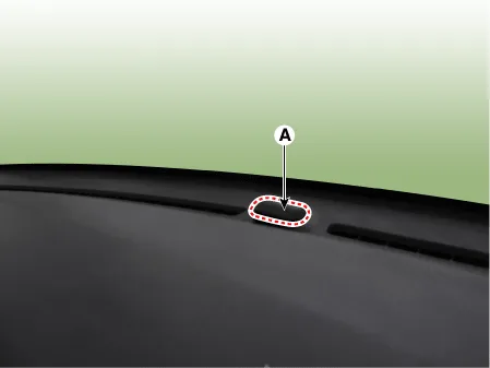
Separate the photo sensor (A) by using a remover.
|
| 14. |
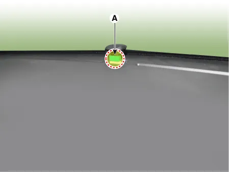
Remove the photo sensor (A), after disconnecting the photo sensor connector.
|
| 15. |
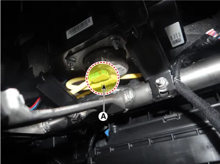
Disconnecting the airbag connector (A) after loosening the mounting nuts (B).
|
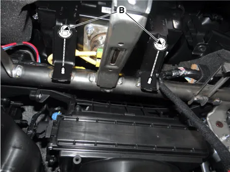
| 16. |
Remove the main crash pad assembly (A), after loosening the mounting bolts and nuts.
|
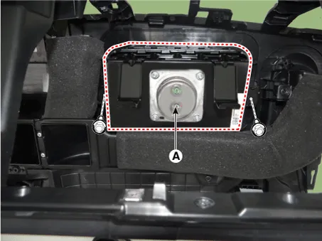
| 17. |
Remove the passenger airbag (A) after loosening the screws.
|
| 18. |
Install in the reverse order of removal.
|
Components and components location Component Location 1. Crash pad center lower panel Repair procedures Replacement Put on gloves to protect your hands.
Components and components location Component Location 1. Main crash pad assembly Repair procedures Replacement Put on gloves to protect your hands.
Other information:
Kia Rio 2017-2023 YB Service Manual: Front Washer Motor
Repair procedures Inspection Front Washer Motor 1. With the washer motor connected to the reservoir tank, fill the reservoir tank with water. • Before filling the reservoir tank wi
Kia Rio 2017-2023 YB Service Manual: Compressor
Description and operation Description The compressor is the power unit of the A/C system. It is located on the side of engine block and driven by a V-belt of engine. The compressor changes the low pressure and low temperature refrigerant gas into the high pressure and high temperature refrigerant gas.
Categories
- Manuals Home
- Kia Rio Owners Manual
- Kia Rio Service Manual
- Maintenance
- Emission Control System
- Engine Electrical System
- New on site
- Most important about car
