Kia Rio: Crash Pad / Cowl Cross Bar Assembly
Components and components location
| Component Location |

| 1. Main crash pad assembly
|
Repair procedures
| Replacement |
Put on gloves to protect your hands. |

|

| 1. |
Remove the cowl top cover. (Refer to "Cowl Top Cover") |
| 2. |
Remove the front wiper motor. (Refer to Body Electrical System - "Front Wiper Motor") |
| 3. |
Remove the main crash pad assembly. (Refer to Crash Pad - "Main Crash Pad Assembly") |
| 4. |
Down the steering column after loosening the mounting bolts. (Refer to Steering System - "Steering Column and Shaft") |
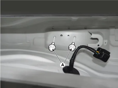
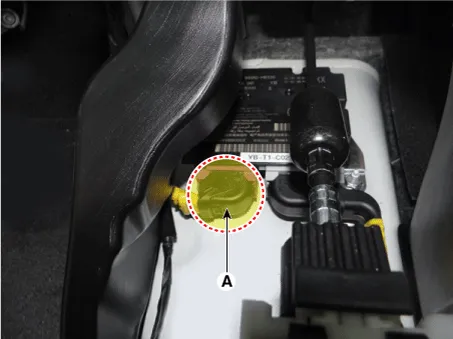
| 5. |
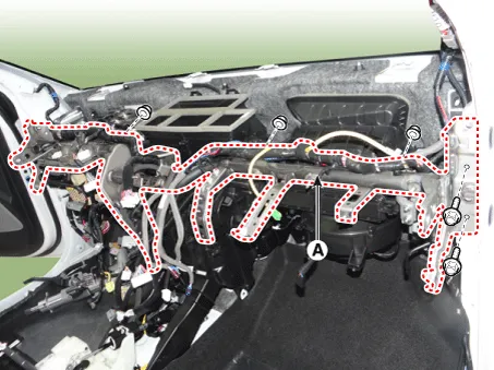
Loosen the cowl cross bar mounting bolts (A).
|
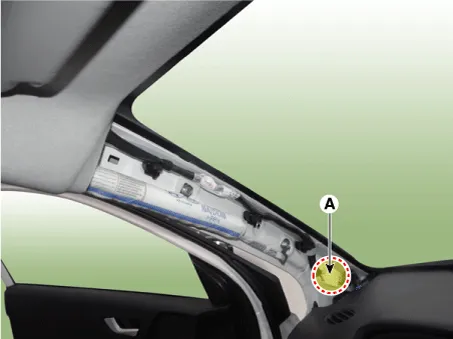
| 6. |
Disconnect the connector (A) and mounting clips in the front pillar. [Driver Side]
[Passenger Side]
|

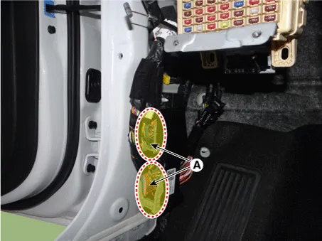
| 7. |
Disconnect the multi box connectors (A), and then remove the wiring mounting clips. [Driver Side]
[Passenger Side]
|
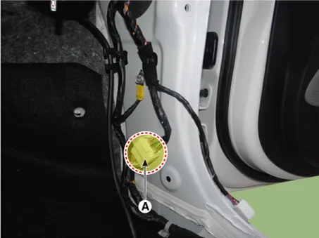
| 8. |
Disconnect the passenger compartment junction box connectors (A).
|

| 9. |
Disconnect the connector (A), and then remove the wiring mounting clips.
|

| 10. |
Disconnect the airbag control module connector (A).
|
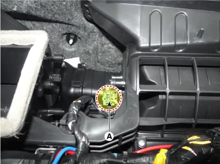
| 11. |
Disconnect the evaporator temperature sensor connector (A), and then remove the wiring mounting clips.
|

| 12. |
Disconnect the BCM unit connector (A) and (B).
|

| 13. |
Disconnect the mode actuator connector (A).
|

| 14. |
Disconnect the blower motor connector (A), and then remove the wiring mounting clips.
|

| 15. |
Disconnect the MOS pet connector (A) and temperature control actuator connector (B).
|

| 16. |
Disconnect the blower intake actuator connector (A).
|
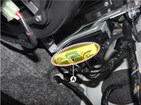
| 17. |
Disconnect the smart key unit connectors (A).
|
| 18. |
Remove the cowl cross bar mounting bolt caps (A).
|

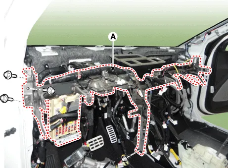
| 19. |
Remove the cowl cross bar assembly (A) after loosening the mounting bolts & nuts. [Driver Side]
[Passenger Side]
|
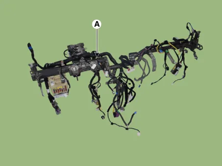
| 20. |
Remove the main wiring harness (A) from the cowl cross bar.
|
| 21. |
Install in the reverse order of removal.
|
Components and components location Component Location 1. Main crash pad assembly Repair procedures Replacement Put on gloves to protect your hands.
Components and components location Component Location 1. Fender assembly Repair procedures Replacement • Be careful not to damage the fender and body.
Other information:
Kia Rio 2017-2023 YB Service Manual: Power Door Mirror Switch
Components and components location Component Driver Power Window Switch Schematic diagrams Circuit Diagram [Non-Folding Mirror Type] [Folding Mirror Type] Repair procedures Removal 1.
Kia Rio 2017-2023 YB Service Manual: Power Window Motor
Components and components location Components [Standard window motor] [Safety window motor] Repair procedures Inspection • When removing with a flat-tip screwdriver or remover, wrap protective
Categories
- Manuals Home
- Kia Rio Owners Manual
- Kia Rio Service Manual
- Steering System
- Engine Electrical System
- Timing Chain
- New on site
- Most important about car
