Kia Rio: Engine Mechanical System / Cylinder Block
Components and components location
| Components |
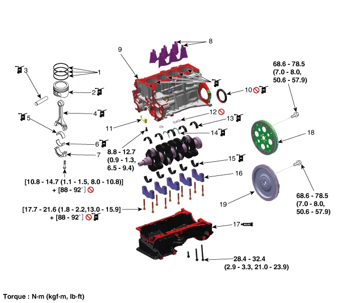
| 1. Piston ring 2. Piston 3. Piston pin 4. Connecting rod 5. Connecting rod upper bearing 6. Connecting rod rower bearing 7. Connecting cap 8. Water jacket insert 9. Cylinder block 10. Rear oil seal |
11. Piston cooling jet 12. O-ring 13. Crankshaft upper bearing 14. Thrust bearing 15. Crankshaft lower bearing 16. Main bearing cap 17. Ladder frame 18. Drive plate 19. Flywheel |
- Water Jacket Insert
- Drive Plate
- Fly Wheel
- Rear Oil Seal
- Piston and Connecting Rod
- Crankshaft
- Cylinder Block
Repair procedures Removal and Installation Thermostat Disassembly of the thermostat would have an adverse effect, causing a lowering of cooling efficiency.
Repair procedures Remove and Installation 1. Remove the cylinder head assembly. (Refer to Cylinder Head Assembly - "Cylinder Head") 2.
Other information:
Kia Rio 2017-2023 YB Service Manual: Keyless Entry And Burglar Alarm
Specifications Specification Item Specification Power source 3 V Operating temperature -22 - 176°F (-30 - 80°C) RF Modulation FSK LF Modulation ASK RF frequency
Kia Rio 2017-2023 YB Service Manual: Hazard Lamp Switch
Repair procedures Inspection 1. Check for continuity between terminals. If the continuity is not as specified, replace the hazard lamp switch. No. Description No.
Categories
- Manuals Home
- Kia Rio Owners Manual
- Kia Rio Service Manual
- Maintenance
- Engine Mechanical System
- Timing Chain
- New on site
- Most important about car
