Kia Rio: Cylinder Block / Cylinder Block
Repair procedures
| Disassembly |
|

|

| 1. |
Remove the engine assembly from the vehicle. (Refer to Engine and Transaxle Assembly - "Engine and Transaxle Assembly”) |
| 2. |
Remove the transaxle assembly from the engine assembly. (Refer to Manual Transaxle System - "Manual Transaxle") |
| 3. |
Remove the flywheel. (Refer to Cylinder Block - "Flywheel") |
| 4. |
Install the engine to engine stand for disassembly. |
| 5. |
Remove the timing chain. (Refer to Timing System - "Timing Chain”) |
| 6. |
Remove the intake manifold. (Refer to Intake and Exhaust System - "Intake Manifold") |
| 7. |
Remove the exhaust manifold. (Refer to Intake and Exhaust System - "Exhaust Manifold") |
| 8. |
Remove the cylinder head assembly. (Refer to Cylinder Head Assembly - "Cylinder Head") |
| 9. |
Remove the water pipe. (Refer to Cooling System - "Thermostat") |
| 10. |
Remove the water temperature control assembly. (Refer to Cooling System - "Thermostat") |
| 11. |
Remove the oil pan and oil screen. (Refer to Lubrication System - "Oil Pan") |
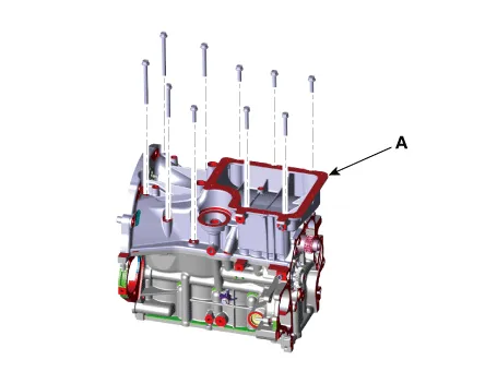
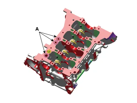
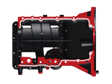
| 12. |
Remove the ladder frame (A). Insert the blade of SST (09215-3C000) between the cylinder block and the ladder frame. Cut off applied sealer and remove the ladder frame (A).
|
| 13. |
Remove the piston and connecting rod assemblies. (Refer to Cylinder Block - "Piston and Connecting Rod") |
| 14. |
Remove the crankshaft. (Refer to Cylinder Block - "Crankshaft") |
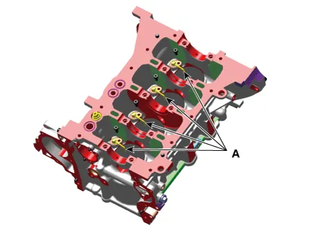
| 15. |
Remove the piston cooling oil jet (A).
|
| Inspection |
Cylinder Block
| 1. |
Remove the gasket material. Using a gasket scraper, remove all the gasket material from the top surface of the cylinder block. |
| 2. |
Clean the cylinder block. Using a soft brush and solvent, thoroughly clean the cylinder block. |
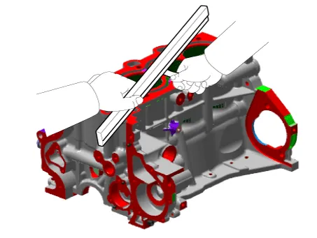
| 3. |
Inspect the top surface of the cylinder block for flatness. Using a precision straight edge and feeler gauge, measure the surface contacting the cylinder head gasket for warpage.
|
| 4. |
Inspect the cylinder bore. Visually check the cylinder for vertical scratchs. If deep scratchs are present, replace the cylinder block. |
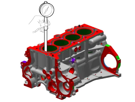
| 5. |
Inspect the cylinder bore diameter. Using a cylinder bore gauge, measure the cylinder bore diameter at position in the thrust and axial direction.
|
| Reassembly |
| 1. |
Remove the crankshaft. (Refer to Cylinder Block - "Crankshaft") |
| 2. |
Remove the piston and connecting rod assemblies. (Refer to Cylinder Block - "Piston and Connecting Rod") |
| 3. |
Install the piston cooling oil jet (A).
|
| 4. |
Install the ladder frame.
|
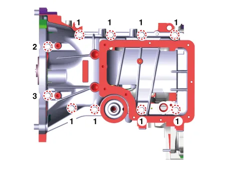
| 5. |
Assemble the other parts in the reverse order of disassembly. |
Repair procedures Disassembly • Use fender covers to avoid damaging painted surfaces.
Other information:
Kia Rio 2017-2023 YB Service Manual: Rear Combination Lamp
Repair procedures Removal Rear Combination Lamp (Outside) 1. Disconnect the negative (-) battery terminal. 2. Remove the rear combination lamp (A) after loosening the mounting screws. 3.
Kia Rio 2017-2023 YB Service Manual: Seat Heater
Components and components location Component Location 1. Seat heater unit (Passenger seat only) 2. Front seat back heater 3. Front seat cushion heater Schematic diagrams Circuit Diagram Repair procedures Inspection 1.
Categories
- Manuals Home
- Kia Rio Owners Manual
- Kia Rio Service Manual
- Timing Chain
- Emission Control System
- Cooling System
- New on site
- Most important about car
