
Kia Rio: Cylinder Block / Water Jacket Insert
Repair procedures
| Remove and Installation |
| 1. |
Remove the cylinder head assembly. (Refer to Cylinder Head Assembly - "Cylinder Head") |
| 2. |
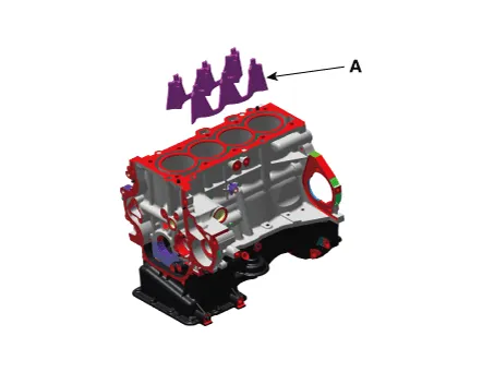
Remove the water jacket insert (A).
|

| 3. |
Install in the reverse order of removal. |
Components and components location Components 1. Piston ring 2. Piston 3. Piston pin 4. Connecting rod 5. Connecting rod upper bearing 6.
Repair procedures Remove and Installation 1. Remove the automatic transaxle . (Refer to Automatic Transaxle System - "Automatic Transaxle") 2.
Other information:
Kia Rio 2017-2023 YB Service Manual: Lane Departure Warning System (LDWS)
Components and components location Components 1. LDWS ON/OFF switch 2. Instrument cluster 3. LDWS unit (MFC) ※ MFC : Multi Function Camera – Function : LDWS, HBA, AEB Description and operation Description System block diagram Components of LDWS
Kia Rio 2017-2023 YB Service Manual: Overhead Console Lamp
Repair procedures Inspection 1. Remove the overhead console lamp assembly then check for continuity between terminals. If the continuity is not as specified, replace the map lamp switch. Removal 1.
Categories
- Manuals Home
- Kia Rio Owners Manual
- Kia Rio Service Manual
- Maintenance
- Filler-Neck Assembly
- CVVT & Camshaft
- New on site
- Most important about car
