Kia Rio: Body Electrical System / Power Door Mirrors
Components and components location
| Component Location |
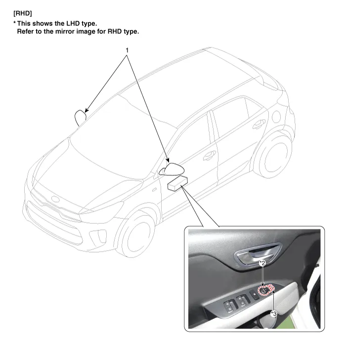
| 1. Power door mirror 2. Power door mirror switch |
3. Power folding mirror switch
|
Repair procedures Removal • When removing with a flat-tip screwdriver or remover, wrap protective tape around the tools to prevent damage to components.
Components and components location Component Driver Power Window Switch Schematic diagrams Circuit Diagram [Non-Folding Mirror Type] [Folding Mirror Type] Repair procedures Removal 1.
Other information:
Kia Rio 2017-2023 YB Service Manual: Condenser
Repair procedures Inspection 1. Check the condenser fins for clogging and damage. If clogged, clean them with water, and blow them with compressed air. If bent, gently bend them using a screwdriver or pliers. 2.
Kia Rio 2017-2023 YB Service Manual: Photo Sensor (FATC only)
Description and operation Description The photo sensor is located at the center of defrost nozzles. The photo sensor contains a photovoltaic (sensitive to sunlight) diode. The solar radiation received by its light receiving portion, generates an electromotive force in proportion to the amount of radiation received which is tran
Categories
- Manuals Home
- Kia Rio Owners Manual
- Kia Rio Service Manual
- Heating,Ventilation, Air Conditioning
- Timing Chain
- Engine Mechanical System
- New on site
- Most important about car
