Kia Rio: Hydraulic System / Line Pressure Control Solenoid Valve
Specifications
| Specification |
|
Item |
Specification |
|
Type |
Normal open |
|
Input voltage |
12 V |
|
Coil resistance |
3.5 ± 0.2 Ω (at 25°C, 77°F) |
|
Frequency |
400 - 1000 Hz |
Components and components location
| Component Location |
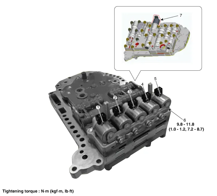
| 1. Overdrive clutch control solenoid
valve (PCSV-A) 2. ON/OFF solenoid valve (SCSV-A) 3. Torque converter control solenoid valve (PCSV-D) 4. Underdrive clutch control solenoid valve (PCSV-C) |
5. 24 brake control solenoid
valve (PCSV-B) 6. Solenoid valve support bracket 7. Line pressure control solenoid valve (LINE_VFS) |
Description and operation
| Description |
| • |
Line pressure control solenoid valve is a VFS (Variable Force Solenoid) type. |
| • |
When TCM supplies variable current to solenoid valve, line pressure is controlled by solenoid valve. |
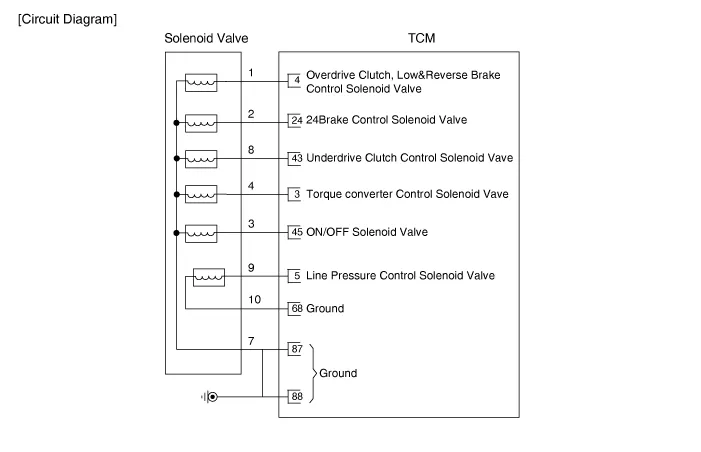
Schematic diagrams
| Circuit Diagram |
Repair procedures
| Inspection |
| 1. |
Switch "OFF" ignition. |
| 2. |
Remove the air cleaner. (Refer to Engine Mechanical System - "Air cleaner") |
| 3. |
Disconnect the main connector (A).
|
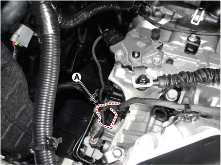
| 4. |
Measure the resistance between ground terminal (10) and signal terminal (9).
|
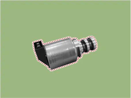
| Removal |
| 1. |
Remove the valve body assembly. (Refer to Hydraulic System - "Valve Body") |
| 2. |
Disconnect the solenoid valve connector. |
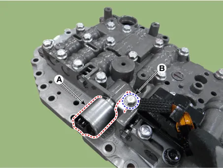
| 3. |
Remove the line pressure control solenoid valve (A) after removing the support bracket by loosening a bolt (B).
|
| Installation |
| 1. |
Install in the reverse order of removal.
|

Specifications Specification Item Specification Type Normal open Input voltage 12 V Coil resistance 3.
Specifications Specification Item Specification Type Normal open Input voltage 12 V Coil resistance 3.
Other information:
Kia Rio 2017-2023 YB Service Manual: Horn
Components and components location Component Location 1. Horn switch 2. Horn relay 3. Horn 4. Clock spring Repair procedures Removal 1. Remove the front bumper assembly.
Kia Rio 2017-2023 YB Service Manual: Rear Parking Assist System
Specifications Specification Item Specification Ultrasonic sensor Voltage rating DC 12V Detecting range 11.8 - 47.2 in (30 - 120 cm) Operation voltage DC 9 - 16 V Operation current
Categories
- Manuals Home
- Kia Rio Owners Manual
- Kia Rio Service Manual
- Engine Control / Fuel System
- General Information
- Emission Control System
- New on site
- Most important about car
