Kia Rio: Hydraulic System / Overdrive Clutch Control Solenoid Valve (PCSV-A)
Specifications
| Specification |
|
Item |
Specification |
|
Type |
Normal open |
|
Input voltage |
12 V |
|
Coil resistance |
3.5 ± 0.2 Ω (at 25°C, 77°F) |
|
Frequency |
50 Hz |
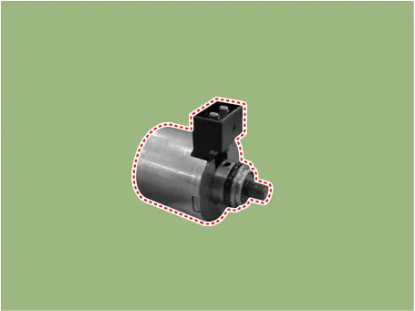
Components and components location
| Component Location |
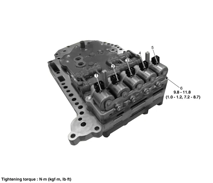
| 1. Overdrive clutch control solenoid
valve (PCSV-A) 2. ON/OFF solenoid valve (SCSV-A) 3. Torque converter control solenoid valve (PCSV-D) |
4. Underdrive clutch control
solenoid valve (PCSV-C) 5. 24 brake control solenoid valve (PCSV-B) 6. Solenoid valve support bracket |
Description and operation
| Description |
| • |
Overdrive clutch control solenoid valve is a PWM (Pulse Width Modulation) type. |
| • |
When TCM supplies current to solenoid valve, hydraulic pressure of OD clutche and LR brake are controlled by solenoid valve. |
Solenoid valve operation table
|
Range |
PCSV-A |
|
N, P |
|
|
1 |
● |
|
2 |
● |
|
3 |
|
|
4 |
|
|
R |
|
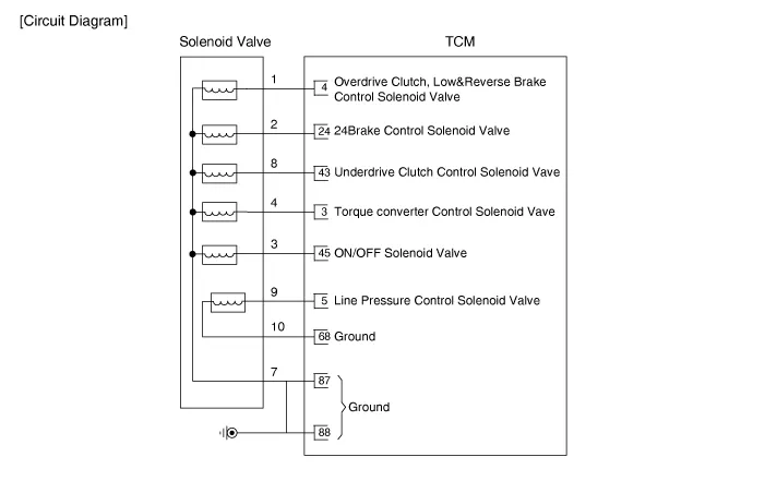
Schematic diagrams
| Circuit Diagram |
Repair procedures
| Inspection |
| 1. |
Switch "OFF" ignition. |
| 2. |
Remove the air cleaner. (Refer to Engine Mechanical System - "Air cleaner") |
| 3. |
Disconnect the main connector (A).
|
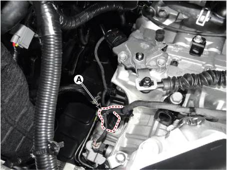
| 4. |
Measure the resistance between ground terminal (7) and signal terminal (1).
|
| Removal |
| 1. |
Remove the valve body assembly (Refer to Hydraulic System - "Valve Body") |
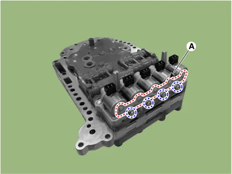
| 2. |
Disconnect the main harness (A).
|
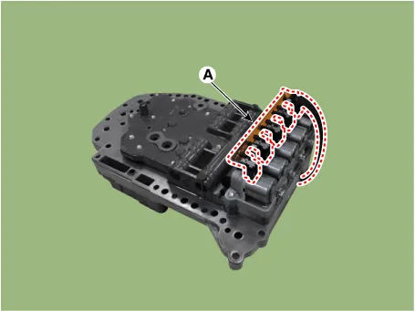
| 3. |
Remove solenoid valve support bracket (A) after loosening the bolts.
|
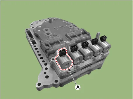
| 4. |
Remove the overdrive clutch control solenoid valve (A).
|
| Installation |
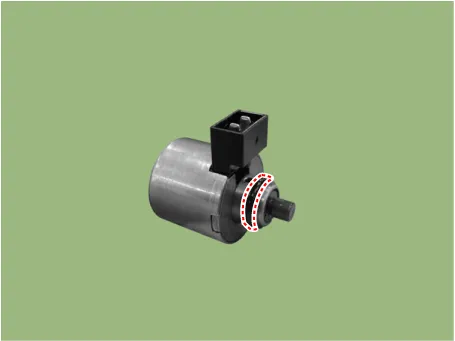
| 1. |
Install in the reverse order of removal. |
When installing, apply the ATF or petroleum jelly to the O-ring to prevent damage.
|

Specifications Specification Item Specification Type Normal open Input voltage 12 V Coil resistance 3.
Specifications Specification Item Specification Type Normal open Input voltage 12 V Coil resistance 3.
Other information:
Kia Rio 2017-2023 YB Service Manual: Power Door Mirror Switch
Components and components location Component Driver Power Window Switch Schematic diagrams Circuit Diagram [Non-Folding Mirror Type] [Folding Mirror Type] Repair procedures Removal 1.
Kia Rio 2017-2023 YB Service Manual: Heater & A/C Control Unit (MANUAL)
Components and components location Components Connector pin function NO. Connector A Connector B 1 Low Battery 2 Common ISG Battery 3 High Illumination (+)
Categories
- Manuals Home
- Kia Rio Owners Manual
- Kia Rio Service Manual
- Timing Chain
- Emission Control System
- Engine Mechanical System
- New on site
- Most important about car
